Downloads
Shapefile data as of 9/3/2025; uploaded on 9/15/2025.
Overview
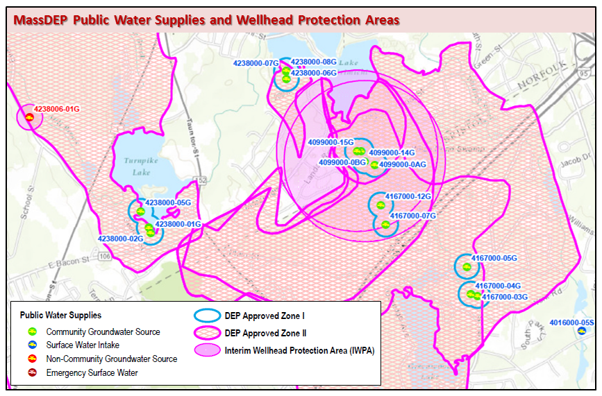
A Zone II is a wellhead protection area that has been determined by hydro-geologic modeling and approved by the Department of Environmental Protection’s (DEP) Drinking Water Program (DWP). In cases where hydro-geologic modeling studies have not been performed and there is no approved Zone II, an Interim Wellhead Protection Area (IWPA) is established based on DEP DWP well pumping rates or default values. Certain land uses may be either prohibited or restricted in both approved (Zone II) and interim (IWPA) wellhead protection areas. For MassDEP's regulatory wording of these zones please see Water Supply Protection Area Definitions.
Approved Wellhead Protection Areas (Zone II)
The statewide datalayer contains DEP Approved Wellhead Protection Areas (Zone II). As stated in 310 CMR 22.02, a Zone II is:
"That area of an aquifer which contributes water to a well under the most severe pumping and recharge conditions that can be realistically anticipated (180 days of pumping at safe yield, with no recharge from precipitation). It is bounded by the groundwater divides which result from pumping the well and by the contact of the aquifer with less permeable materials such as till or bedrock. In some cases, streams or lakes may act as recharge boundaries. In all cases, Zone IIs shall extend up gradient to its point of intersection with prevailing hydrogeologic boundaries (a groundwater flow divide, a contact with till or bedrock , or a recharge boundary)."
DEP Zone II and public water supply (PWS) data are closely linked, and DEP Zone II data should be used in association with the DEP Public Water Supply datalayer (PWSDEP_PT). During the approval process each Zone II is assigned a unique ID (ZII_NUM) by DEP DWP. The DEP PWS and Zone II datalayers use the ZII_NUM to link protected PWS sources to their approved Zone II. Since some PWS sources within a Zone II may not have been used to delineate that Zone II, the ZII_NUM item can be used to identify the specific wells for which a Zone II was delineated. If the DEP PWS datalayer item ZII_NUM is equal to 0 than that PWS source has no Zone II and should therefore have an Interim Wellhead Protection Area (IWPA).
The statewide polygon layer is named ZONE2_POLY. A cartographic layer of Zone II's with internal boundaries dissolved out is named ZONE2_POLY_DISSOLVE.
Zone II Manuscripts
Zone II delineation maps, based on USGS (1:25,000) topographic quadrangles, are submitted to the DEP DWP as a requirement for Zone II approval and are considered to be the Department’s "official" Zone II maps. Traditionally these maps were submitted by consultants in hardcopy/analog format. Since 1999, Zone II data developed under DEP’s Source Water Assessment Program (SWAP) is submitted by the consultant in a digital (ESRI shapefile) format. It is strongly recommended that if Zone IIs are to be used in site level analysis, the original hardcopy manuscript documents, located at DEP's Boston Office, be referred to for evaluation of any critical, site specific information. Please refer to the section below on data maintenance for DEP DWP contact information.
Zone II Methodology
Historically the "official" Zone II paper maps were used to recompile Zone II boundaries into the DEP Water Supply Protection Atlas, which consisted of stable mylar overlays based on the USGS 7.5 minute (1:25,000) topographic quadrangles. Prior to January 1996 Zone IIs were automated using the following methodology. After the technical reports were reviewed for completeness, the Zone II boundaries were transferred to a USGS-based stable mylar overlay. The Zone IIs were then inked onto the Water Sources overlay using a size 0 (.35 mm) pen and tablet digitized by GIS Program staff.
As of January 1996 the automation steps of recompiling the Zone II boundary onto the DEP Water Supply Protection Atlas Water Source overlay and tablet digitizing have been abandoned. Zone II boundaries are currently generated by one of the following methodologies:
- After the technical reports are reviewed for completeness and approved by DEP DWP technical services staff the DEP GIS Program is provided an analog copy of the "official" Zone II map. The Zone II map is scanned into a .tif image and then converted to an ESRI GRID image. Using the GRID as a background feature a minimum of four (4) tics are added to an empty Zone II template coverage. Rasterized Zone II data is converted to vector format by tracing the Zone II boundary on the underlying GRID. The vectorized Zone II boundaries are transformed into NAD83 Massachusetts state plane meter coordinates. New Zone IIs are appended to the statewide Zone II datalayer and regionalized.
- After the technical reports are reviewed for completeness and approved by DEP DWP technical services staff the DEP GIS Program is provided a digital copy of the "official" Zone II boundary generated by the consultant. New Zone IIs are appended to the statewide Zone II datalayer and regionalized.
Zone II Attributes
The ZONE2_POLY feature class contains the following fields:
| Name | Description |
|---|---|
| ZII_NUM | The unique number assigned by DEP DWS to identify each Zone II |
| SUPPLIER | Name of the PWS purveyor (supplier) according the MassDEP Water Quality Testing System (WQTS) RDBMS at the time of update. |
| TOWN | The municipality which the PWS source is primarily associated, as determined by the embedded (1-351) town-id in the PWS source identifier (SOURCE_ID), which is not necessarily the town where the source is physically located. |
| AREA_ACRES | The area of the Zone II in acres |
| PWS_ID | First seven digits of the DWP-assigned PWS source identifier (SOURCE_ID, which is used to relate PWS source locations to WQTS and other DEP PWS datalayers). |
Interim Wellhead Protection Areas (IWPA)
In the absence of an approved Zone II, DEP has adopted the Interim Wellhead Protection Area (IWPA) as the primary, protected recharge area for PWS groundwater sources. For PWS sources that pump less than 100,000 gallons per day (GPD), the IWPA radius is proportional to the pumping rate in gallons per minute (GPM). Pumping rate is determined by DEP DWP based on one of the following methods, DWP approved pumping rate, metered data or Title 5 flow rate. The formula used for calculating the PWS well point buffer radius in feet is:
Radius = ( 32 x pumping rate in GPM ) + 400
The minimum IWPA radius is 400 feet, the maximum (default) radius reached at 100,000 GPD (70 GPM) is 2,640 feet (1/2 mile). In instances where DWP pumping rate information is unavailable DWP approved default radius values are assigned based on PWS well classification. The default radius for community class PWS groundwater sources (GW) is 2,640 feet (804.6 meters). The default radius for non-community sources is 750 feet (228.6 meters) for Non Transient (NTNC) wells and 500 feet (152.4 meters) for Transient (TNC) wells.
The IWPA layer contains variable width IWPA buffers for BOTH approved community and non-community groundwater sources in the DEP PWS datalayer, which do not have an approved Zone II.
IWPA Methodology and Attributes
The PWS groundwater source locations are buffered to produce IWPAs. Buffer radii values are determined from the best available pumping rate information. Internal boundaries between overlapping IWPAs are then dissolved out. IWPA polygon features may therefore represent a single IWPA or the combined area of overlapping IWPAs. Because internal boundaries have been removed, IWPA polygons cannot be related to PWS source points and there is no programmatic attribution included with the DEP IWPA datalayer. The resulting dissolved layer, IWPA_POLY_DISSOLVE, is stored in an Orace/ArcSDE, along with the undissolved version, IWPA_POLY.
The IWPA_POLY feature class contains the following fields:
| Name | Description |
|---|---|
| SOURCE_ID | DWP-assigned PWS source identifier (first 7 digits conform to PWSID). The SOURCE_ID is used to relate PWS source locations to WQTS and other DEP PWS datalayers. |
| TYPE | The type of PWS associated with the IWPA, according to WQTS or the DWP Zone II database: ESW = Emergency Surface Water GW = Community groundwater well NTNC = Non-Transient Non-community TNC = Transient Non-Community |
| SITE_NAME | For community sources this is the source name (S_NAME) as listed in WQTS, for non-community sources this is the public water supply name (PWS_NAME) as listed in the WQTS table. For proposed sources, which are not tracked in WQTS, this is the source name as listed in DEP DWP’s Zone II database. |
| SUPPLIER | Name of the PWS purveyor (supplier) according the MassDEP Water Quality Testing System (WQTS) RDBMS at the time of update. |
| TOWN | The municipality which the PWS source is primarily associated, as determined by the embedded (1-351) town-id in the PWS source identifier (SOURCE_ID), which is not necessarily the town where the source is physically located. |
| IWPA_FT | Radius in feet of the IWPA |
| PWS_ID | First seven digits of the DWP-assigned PWS source identifier (SOURCE_ID, which is used to relate PWS source locations to WQTS and other DEP PWS datalayers). |
Zone I
The MassDEP Wellhead Protection Areas (Zone I) layer is maintained in a MassDEP Enterprise Geodatabase as a polygon feature class named ZONE1_POLY. A cartographic layer of Zone I's with internal boundaries dissolved out is named ZONE1_POLY_DISSOLVE.
As stated in 310 CMR 22.02, Zone I means the protective radius required around a public water supply well or wellfield. For public water system wells with approved yields of 100,000 gpd or greater, the protective radius is 400 feet. Tubular wellfields require a 250-foot protective radius. Protective radii for all other public water system wells are determined by the following equation: Zone I radius in feet = (150 x log of pumping rate in gpd) - 350. This equation is equivalent to the chart in the Guidelines and Policies for Public Water Systems. A default Zone I radius or a Zone I radius otherwise computed and determined by the Department shall be applied to transient non-community (TNC) and non-transient non-community (NTNC) wells when there is no metered rate of withdrawal or no approved pumping rate. In no case shall the Zone I radius be less than 100 feet.
Zone I Methodology and Attributes
The PWS groundwater source locations are buffered to produce the Zone I features. Buffer radii values are determined from the best available pumping rate information as provided by the MassDEP DWP. For tubular well fields a polygon is created by buffering the perimeter of the wellfield by 250 feet.
Because Zone I radii are relatively small compared to potential spatial errors in well location, and restrictions on allowable activities relative strong, the GIS delineations are advisory only. Real world decisions should be based on field verification of the well locations and measurements of distance from there.
The ZONE1_POLY feature class contains the following fields:
| Name | Description |
|---|---|
| SOURCE_ID | DWP-assigned PWS source identifier (first 7 digits conform to PWSID). The SOURCE_ID is used to relate PWS source locations to WQTS and other DEP PWS datalayers. |
| TYPE | The type of PWS associated with the IWPA, according to WQTS or the DWP Zone II database: ESW = Emergency Surface Water GW = Community groundwater well NTNC = Non-Transient Non-community TNC = Transient Non-Community |
| SITE_NAME | For community sources this is the source name (S_NAME) as listed in WQTS, for non-community sources this is the public water supply name (PWS_NAME) as listed in the WQTS table. For proposed sources, which are not tracked in WQTS, this is the source name as listed in DEP DWP’s Zone II database. |
| SUPPLIER | Name of the PWS purveyor (supplier) according the MassDEP Water Quality Testing System (WQTS) RDBMS at the time of update. |
| TOWN | The municipality which the PWS source is primarily associated, as determined by the embedded (1-351) town-id in the PWS source identifier (SOURCE_ID), which is not necessarily the town where the source is physically located. |
| ZONE1_FT | Radius in feet of the Zone I |
| PWS_ID | First seven digits of the DWP-assigned PWS source identifier (SOURCE_ID, which is used to relate PWS source locations to WQTS and other DEP PWS datalayers). |
Maintenance
These GIS layers are maintained by the MassDEP GIS Program in cooperation with MassDEP DWP. The MassDEP GIS Program updates Zone II, IWPA and Zone I data in conjunction with updates to the MassDEP Public Water Supply Source layer and in accordance with the DWP new source approval schedule. Besides adding new Zone II, IWPA and Zone I areas, updates may include modifying existing areas and removing superseded Zone IIs. Updated layers are then published through MassGIS.
Beginning with the October 2015 update Zone I's are included in the data distributed to the public.
General and technical questions regarding MassDEP well head protection areas should be referred to the MassDEP Drinking Water Program (email:program.director-dwp@mass.gov). GIS-related questions concerning these or other MassDEP water supply layers can be referred to the MassDEP GIS Program Director (email: Kashif.Rashid@mass.gov).
| Last updated: | September 15, 2025 |
|---|