Introduction
The Division of Capital Asset Management and Maintenance (DCAMM) manages several hundred million dollars’ worth of projects yearly in keeping with the mission “…to serve the citizens of the Commonwealth by providing professional, comprehensive services to state agencies in public-building design, construction, maintenance and real estate.”
Post construction, the data from these projects are used to support diverse activities of state agencies to which project data are delivered.
In the early 2000’s, a number of DCAMM project managers and several architects, engineers, and contractors engaged by DCAMM began using Building Information Modeling (BIM) technologies on DCAMM
projects. The primary focus of these activities was controlling construction costs, through minimizing “clashes” BIM proved to be an effective tool in detecting and resolving many of these conflicts before construction, thus reducing the number of change orders in construction projects.
As the department became more familiar with BIM technology, and as increasing numbers of architects, engineers, and constructors began using BIM, DCAMM recognized that a standardized approach was required in order to maximize the potential of BIM in design, construction, and facilities management and maintenance.
A BIM Standards Committee, comprised of representatives of the major business units of the agency was formed, and in early 2012,proposals for BIM consultancy services were solicited. AEC Infosystems, Inc. of Baltimore, Maryland was awarded a contract in August of that year to assist DCAMM in its BIM implementation activities. The DCAMM BIM
Guide is one of the items delivered to DCAMM as part of this engagement. Two others, a DCAMM BIM Execution Plan
template, and a BIM Roadmap for internal use, are the other documents called for in this contract.
It is recognized that BIM software is constantly being improved, and that DCAMM will adopt and adapt to changing technologies and business practices when such technologies and practices are of benefit to the agency and the people of Massachusetts. Periodically, this guide and associated documents will be revised to reflect these
changing conditions.
BIM Steering Committee 2015
Credits & Acknowledgements
Charles D. Baker, Governor
Karyn E. Polito, Lieutenant Governor
Kristen Lepore, Secretary, Administration and Finance
Division of Capital Asset Management and Maintenance
Carol Gladstone, Commissioner, Division Capital Asset Management and Maintenance
Elizabeth Minnis, Deputy Commissioner, Office of Planning, Design and Construction (OPDC)
Michael Costello, BIM Project Manager (OPDC)
Vincent Cirigliano, Deputy Director, Facilities Management, Planning and Design
Shirin Karanfiloglu, Director of Programming, OPDC
George Matthews Deputy General Counsel
Ellen Whittemore, Deputy Director of Programming
Ann Storer, Program Manager
Ron Ferrara, Construction Project Manager
Craig Holmes, Senior Cost Manager
Finbar Crean, DCAMM CIO
DCAMM BIM Steering Committee: Executive Administration
Michael Costello, Chair
Scott Calisti Fred Manigat
Vincent Cirigliano Mel Klayman
Antonio Leite Jeffrey Novak
Stephen O’Connor Edward Ransom
Ann Schiro Catherine Walsh
Primary Guide Authorship
AEC Infosystems, Inc.
Dianne Davis, CSI, BsA, Director, BIM Lean Processes and Services
Didrik Thede, CSI, IFMA, Director, Facility Information Infrastructure
Michael Hansen, MBA, Contracts
Henry Berger, Architect, Manager, BIM Services
Additional Information Provided by:
Erik Sanford, VDC/BIM Director, Dimeo Construction
Christopher Pechacek, Director/Design Manager, McCarthy Building Systems
Igor Starkov, EcoDomus
James Vandezande, AIA, HOK BIM Manager
Michael Schroeder, BIMJet, Inc.
Kurt L. Dettman, Strategic Enterprise Technology, Inc.
Kristen Hill, InsideOut Consulting
Reference Guides and Standards:
VA BIM Guide LACCD BIM Guide National BIM Standard
AOC BIM Guide UK BIM Protocols Penn State BIM Execution Plan
Massport BIM Guidelines CSI OmniClass AGC LOD Specification
About this Guide
The DCAMM Building Information Modeling (BIM) Guide establishes requirements for the BIM services, BIM project execution, and submissions. BIM is used for all phases of DCAMM projects. Current law allows the Program Designer to complete the Study Phase and continue into final Design.
This guide complements The Designers Procedure Manual in that BIM is a primary tool for project information development. It also complements the Owner-CM or GC Agreement. Any conflict between this BIM Guide and the contract documents between DCAMM and the Designer, or the CM/GC, will be resolved with the respective
contract documents taking precedence.
The guidelines are based on BIM “best practices”, Lean project approaches, industry and DCAMM data standards. These are all part of DCAMM’s strategy to maximize BIM’s analytical and information development capability for project submissions and facility lifecycle data for its stewardship role.
BIM and Lean knowledge are expected from DCAMM projects teams. Adherence to the guidelines ensures process uniformity and data in models. A Lean collaboration environment maintains consistency in procedures from
different service providers.
Appendix A. contains the DCAMM BIM Use descriptions, which will be updated as the industry evolves.
DCAMM has also developed a BIM Execution Plan (BIMxP) template to standardize and partially
automate a team’s BIM documentation.
Guide Includes:
- DCAMM BIM vision and value proposition
- Collaboration for Lean BIM projects
- BIM Execution Planning and BIM Uses
- Data standards, modeling and construction documentation requirements
- Model and project contract documents development and submissions
- Glossary
Reference Standards:
- BIM Execution Plan (BIMxP) Template
- DCAMM Facility Management Information
- Asset Naming Conventions
- OmniClass Tables, MasterFormat, and Uniformat, Construction Specification Institute (CSI)
- Level of Development (LOD) 2013, AGC/AIA BIMForum
- National BIM Standard (NBIMS), National Institute Building Sciences (NIBS)
- DCAMM CAD Standard The Designers Procedure Manual - Data Verification and Collection Form Set 2-26-14.xlsx
The DCAMM BIM Guide and CAD Standards are available at the DCAMM website.
BIM Definitions and Model Types
Terminology can challenge team communication. To assist teams, DCAMM has selected industry terms for models developed and submitted throughout the project lifecycle. Additional project terms are located in the Glossary.
National BIM Standard Definition
“A Building Information Model (BIM) is a digital representation of physical and functional characteristics of a facility. As such it serves as a shared knowledge resource for information about a facility forming a reliable basis for decisions during its life-cycle from inception onward.”
DCAMM Model Types
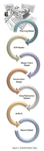
Planning Model is a simple model used for preliminary studies, early project planning, and programming. Space and area tools are used to define programming needs, space calculations, schematic massing, blocking and stacking, massing for site location, and early energy analysis to rapidly explore multiple options. These models can be used as a basis for design development.
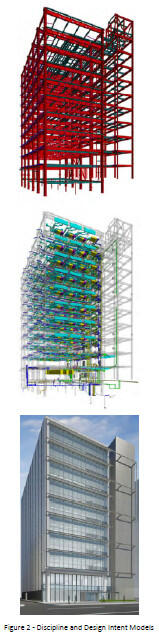
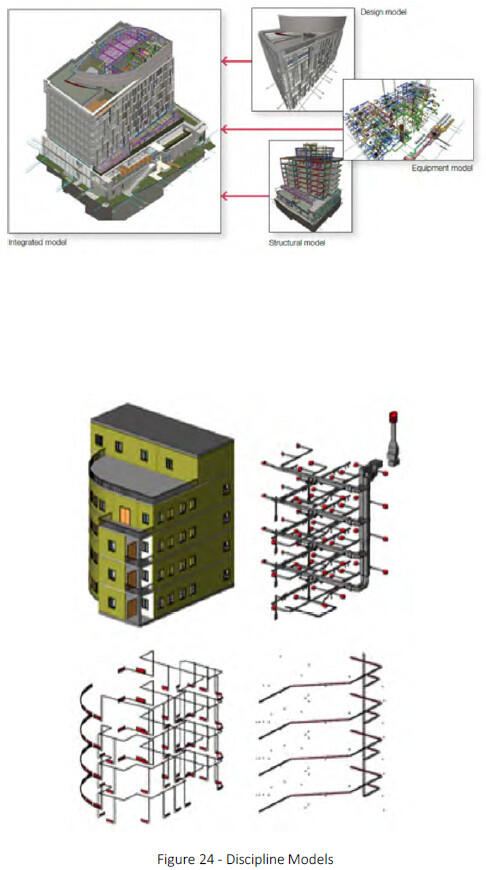
Work in Progress (WIP) are specific discipline models. Examples are architecture, structure, MEP. These models are combined or federated 1 for design development, and BIM Use execution. These models are used during project progress reviews. The reviewed and approved WIP models are federated into the Design Intent Model.
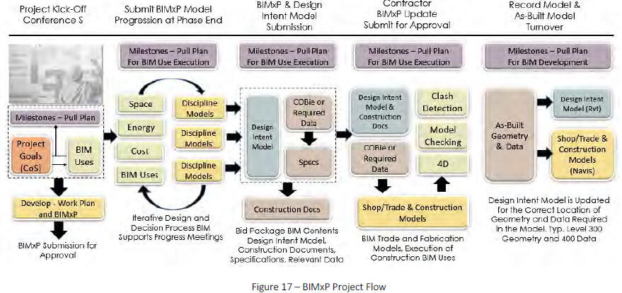
Design Intent Model supports design execution, decision support, clash avoidance, and final construction documentation. The Design Intent Model is a contract deliverable for submission to DCAMM. The Design Intent Model contents are updated to reflect as-built conditions to become the Record Model.
Construction Coordination Model is the further development of the Design Intent Model by the CG team. The shop/trade models are developed by the sub-contractors. Smaller digital mock-ups may be created by the construction team to detail specific elements, intersection of building conditions, or systems for constructability review.
Record Model is a contract requirement and is the basis of the DCAMM FM model. It is the Design Intent Model (.rvt) updated to show as-built locations. It does not have the same level of construction detail as the As-Built Model. It may be used by commissioning. Equipment data and other information is updated in this model.
As-Built Model file is a contract requirement. It is typically a Navisworks ® file and includes shop models and drawing information from trades and fabricators with the as-installed conditions. This file may also include point cloud data.
Parametric Modeling provides additional capability to BIM authoring tools. API’s and rules based programming is used to produce elements and objects for rapid modeling exploration. Parametric modeling moves BIM one-step closer to simulation. This is useful during design option development.
Digital Mock-Ups are sub-models of design details to study design and constructability issues. These are used in Studies, design development and construction coordination.
Importance of BIM Uses – “Starting with Why”
Different from CAD, BIM integrates numerous design and construction tasks. BIM automates or eliminates many non-value-add tasks in traditional design and drafting, and streamlines other value-add activities.
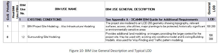
Modeling activities important to DCAMM are described in Appendix A. of this document. These “BIM Uses” describe WHY, WHAT, WHO, the average Level of Development (LOD), data requirements, tools, and the expected outcome of the activity.
Project scope and Conditions of Satisfaction (CoS) dictate the BIM Uses executed on a project. The team should consider the BIM Use description as a minimum effort, and a point of discussion in developing the project BIM effort and execution schedule. DCAMM also expects BIM to be used for:
- Program development and validation
- Estimation and quantities when applicable
- Energy modeling when applicable
- Visualization for stakeholder decisions
- “Clash” avoidance/detection during design and construction
- Construction Documentation
- The Design BIM Manager will participate in early scope and project CoS meetings to identify the project BIM Uses. These BIM Uses and execution schedule will be documented in the BIM Execution Plan (BIMxP).
Types of BIM Uses in Guide
- Existing Conditions
- Building System Authoring
- Analysis and Reporting
- Sustainability, Energy, LEED Design
- Constructability Reviews and Coordination
- Documentation, Drawings, Specs
- Commissioning and Handover
- Facilities and Data Management
Phase Names
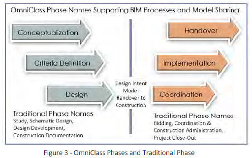
DCAMM is transitioning to OmniClass Phases to support BIM. The diagram shows the relationship of the new phases in the BIMxP to traditional phases as used in the Designer’s Manual
1 Federated - WIP models (architecture, electrical, structural, etc.) are combined or federated in the project BIM collaboration environment.
1 - Why Bim at DCAMM
The decision to implement BIM is part of a significant multi-year transformation to meet DCAMM’s expanded facility lifecycle mission. BIM supports four of DCAMM’s six strategic goals to improve:
- Facility performance
- Customer service and satisfaction
- Building project delivery
- Energy efficiency and sustainability
BIM is the predominant tool and process of DCAMM service providers. This confirms DCAMM’s belief in the importance of this industry change, and the benefits of BIM on projects.
When used successfully, BIM offers higher quality design and standardized information for more informed project decisions. Project information is more coordinated, reliable and reusable, allowing DCAMM teams to be more productive and design solutions functional, cost effective, and sustainable.
BIM supports various forms of simulation and reporting such as energy modeling and conflict “clash” detection. Facilities information, created during a BIM project, can be repurposed, greatly reducing information handover for post construction facility operations.
As a Six-Sigma organization, BIM and Lean principles are equally essential enablers in DCAMM’s strategy for innovative project delivery and lifecycle asset management. DCAMM expects BIM to be used within a Lean environment conducive to collaborative information flow, communication, analysis, and problem solving. Lean approaches to design and construction promote safe, timely, and productive project delivery, and information handover to support commissioning and operations.
2 - DCAMM BIM Projects
DCAMM is committed to designing buildings that incorporate universal access, sustainable design and energy efficiency. BIM will be used to develop high performing; well-coordinated designs that deliver desired project outcomes.
BIM is useful on all types and phases of DCAMM projects. BIM will be required for new construction, substantial renovation, major maintenance and improvement, and extension projects with a wide range of alternatives or significant financial costs. Additionally, service providers are using BIM in Studies. Building projects with an estimated value of $1 million and above should be reviewed by DCAMM for BIM use.
2.1 DCAMM Procurement Methods
DCAMM uses several project delivery methods, under Massachusetts General Laws (MGL), Chapter 30, 149, 149A, and 25A. Updated procurement options are published on the DCAMM Website.
A team’s BIM experience, collaboration, and data management capabilities are important considerations during project selection. The Designer Selection Board will review the team’s BIM, Lean collaboration, and data capabilities and select the best-qualified team.
Design Bid Build Chapter 149
D-B-B is the traditional public bidding method, choosing a contractor based on lowest responsive bid after design completion. This remains the most common contractor selection method for repair and renovation projects and smaller new projects in construction.
Energy Design/Build Chapter 25A
This design/ build procurement involves the selection of a contractor’s proposal based on thirty (30%) percent Schematic Design to achieve energy and water savings through selected improvements which are paid for, in part, through savings.
Construction Manager at Risk Chapter 149A
Construction Manager at Risk or CM@Risk is used for building projects over $5M as authorized by MGL Ch. 149A. A construction management firm provides a range of pre-construction and construction management services Selection of a CM is a qualification-based process with cost and fee considerations. Most of the hard costs associated with the work are based on competitive bids. A guaranteed maximum price (GMP) is negotiated early in construction after some buyout of the work.
3 - Intergrating Industry Initiatives
BIM collaboration, communication protocols, modeling processes, and data standards development remains fragmented across industry organizations, discipline silos, and competing software vendors. As an owner, DCAMM must bring together several disparate industry initiatives in this guide to gain BIM efficiencies and consistency across projects.
The National BIM Standard (NBIMS), National and DCAMM CAD Standards (NCS), Construction Specification Institute (CSI) OmniClass, Associated General Contractors (AGC) and AIA Level of Development (LOD) 2 , BuildingSMART Alliance (BSa) open data standards (IFC) and Lean Construction Institute (LCI) principles3, are essential enablers of DCAMM’s strategy for innovative project teaming, and BIM data management. How these are used on a project is documented in the BIM Execution Plan (BIMxP). DCAMM expects teams to understand these concepts and utilize them on projects.
3.1 Model Level of Development (LOD)
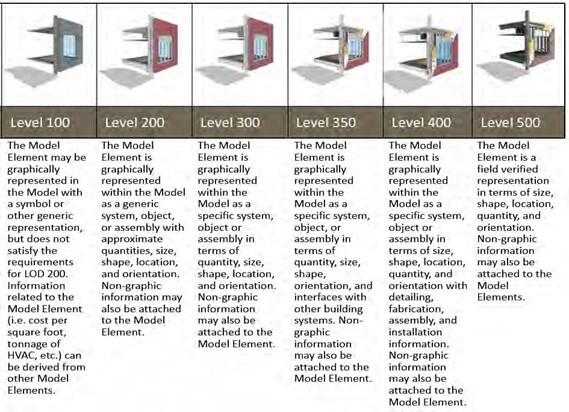
Virtual collaboration requires clear understanding of BIM sharing protocols, geometry and information reliability. The AIA/AGC Level of Development (LOD) Specification, published in 2013, is incorporated, as a reference standard in DCAMM BIM projects. BIM managers use LOD to explain information requirements needed at various points in model development.
Level of Development (LOD) has evolved to convey BIM data4 reliability. It helps project teams and owners clearly define BIM modeling effort and requirements in a BIM Use or a final deliverable.
DCAMM is using LOD to:
- provide a standard that can be referenced in contracts and in the BIMxP
- define general modeling effort in a BIM Use
- as a reporting mechanism for model and data progression in the project BIMxP
- communicate model development and information reliability
- LOD is not uniform for all models and all elements through the project phases. Rather LOD is related to the BIM Uses and objects/elements used in the project.
3.1.1
AGC LOD definitions are general and should be interpreted by the team to arrive at a project specific level for project objects and elements.
Note: Level of Detail (LoD) and Grade)5 addresses the geometric detail of objects, from a simple bounding box to a product specific representation. Grade is the UK distinction for data reliability. DCAMM has not used Level of Detail or Grade in this BIM Guide.
3.2 Industry Data Standards
DCAMM utilizes several national standards to streamlining data integration, increase the value of project data, an maximize the sharing and re-use of the information fo design, construction, and the facility lifecycle.
- The National BIM Standard (NBIMS) 6 is an open source standard for BIM. Major products of NBIM are the Information Exchanges (i.e.), which define purpose, components, and attributes for BIM development. Industry Foundation Classes, (IFC)7 are documented in NBIMS information exchanges.
- National CAD Standard (NCS)– NBIMS is incorporating the National CAD Standards with BIM to support drawing production and publishing of construction documents. DCAMM has CAD standards based o NCS. DCAMM will review and update its Drawing an Publishing Requirements as necessary.
- Construction Specification Institute - Omniclass is faceted building information classification made up o interrelated tables that define the built environment DCAMM currently uses UniFormat and MasterFormat in its projects. These are being integrated into OmniClass. As part of the move to BIM, DCAMM i transitioning to OmniClass™ Table 13 for space classification.
- UniFormat and MasterFormat - These are still in us in the BIMxP. The use of UniFormat and OmniClas will be defined in the BIMxP for the project. Cos Estimation is delivered in Uniformat II in the Stud Phase and in both Uniformat II to Level 3 and CS MasterFormat in the Design Phase.
- DCAMM Equipment and Room Data Requirements - DCAMM has identified data and attribute requirements for buildings, rooms, spaces and equipment required during the project and at model turnover.
- The design team will use the - Data Verification and Collection Form Set 2-26- 14.xlsx to identify the elements in the project that are requirements at handover and document the LOD of these objects
during design and construction.
The Design BIM Manager will add the appropriate attribute fields of objects to support the DCAMM requirements.
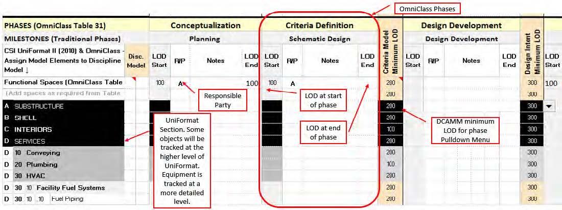
3.2.1 LOD and UniFormat in the BIM Execution Plan (BIMxP)
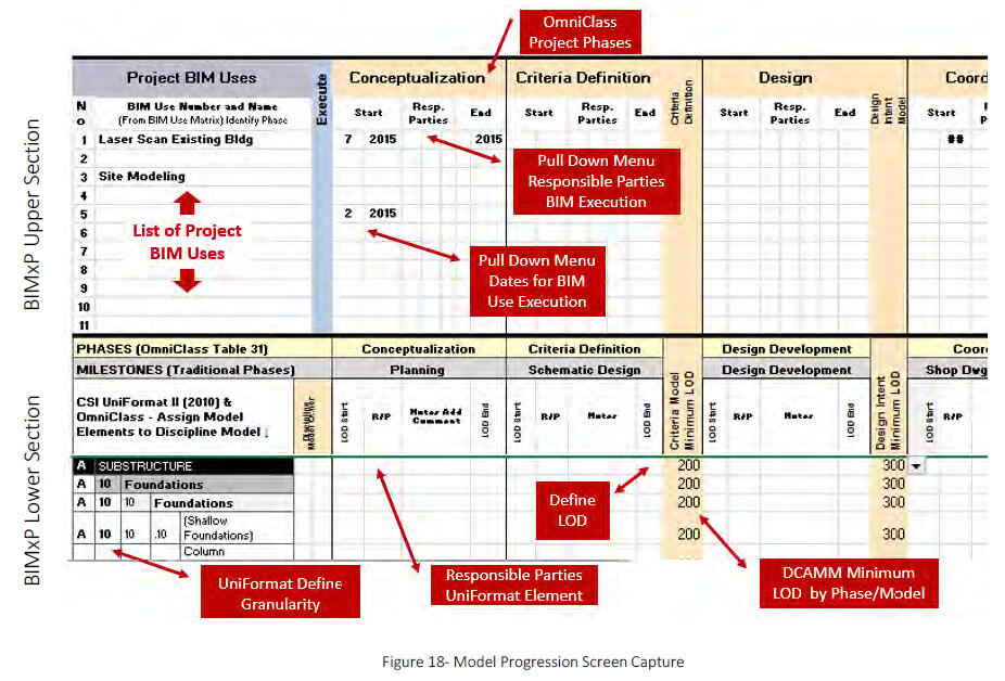
DCAMM uses LOD, UniFormat, and OmniClass Phases in the BIMxP Template (Tab 5), to define model content and report model progression. At the beginning of the project, the Design BIM Manager will determine the UniFormat level of the objects and elements to be tracked and the using LOD in the model progression matrix. At the beginning and end of each phase, the LOD will be updated to show model progression. The DCAMM project manager will review the LOD identified in the BIMxP.
A typical LOD is assigned to DCAMM BIM Uses to be selected for the project. By aligning LOD with the required BIM Use for a project, the team has the minimum geometric detail and reliability of information required for the activity. Combining LOD and a BIM Use reduces over modeling or not having the correct information (LOD) in the model when needed.
Combined with a BIM Use definition, the LOD specification provides a standardized way of defining model element reliability, and an understanding of model element progression through the project. The DCAMM BIMxP has a worksheet that identifies the minimum LOD by phase.
3.3 Lean Design and Construction
DCAMM is transitioning to Lean for BIM project management. By utilizing Lean “thinking,” a team can structure its BIM development efficiently and use its communication protocols effectively to achieve the project CoS9, and other specified design performance requirements. These five core principles and process improvements help maximize BIM use on DCAMM projects.
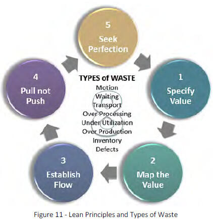
3.3.1 Lean Principles
Lean principles and tools establish a framework for BIM project management
- Specify Value - According to what the customer wants and is willing to pay for. Over-modeling is wasteful, while
under- modeling affects model support for project use. - Map Value - Map activities that deliver the highest value using the least amount of resources. BIM can be streamlined by identifying its “value stream” – within the project flow. Define what is modeled, when, for what purpose, and how to do it most efficiently. This information is considered a BIM Use. The processes mapped by the team should deliver on the CoS, providing useful information at the right stage of the project.
- Establish Flow - BIM is a primary means of developing project information. Project flow can be accomplished by aligning BIM Use execution to team process mapping. This model progression is identified in the BIMxP. It is in the best interest of all parties to hold regularly scheduled meetings for model development and review. Models typically help teams identify issues earlier in the design process. The models can minimize misinterpretations.
- Pull – Don’t Push - This Lean principle starts with the project goal or outcome and “pull” toward it, performing only the work needed to accomplish the goal. Accomplishing this requires planning step-by-step backward from the goal or outcome to determine what each step in the process requires from the one before it. Later steps determine what the earlier steps should be and when they should occur. Nothing should be modeled that is not required by a later step or submission in the process.
- Seek Perfection = Plan, Do, Check, Act (“PDCA Cycle”) is the methodology for continuous improvement. The PDCA Cycle encourages the BIM Managers to examination BIM activities to identify bottlenecks, their causes, and ways to eliminate issues in the future. BIM is non-linear. Some elements will be modeled to a higher LOD than others will during the project. Look for processes that can be performed in parallel, automated or eliminated, in order to increase BIM quality and reduce the time and effort to an outcome.
- Plan - Use the BIMxP and Project Value Stream Mapping and Pull Planning to identify the BIM Uses that meet the project Conditions of Satisfaction (CoS)
- Do - Train and support the project BIM team in well understood and lean collaboration. Understanding what is needed, when, will reduce breaks in flow.
- Check - Model progression through periodic project team meetings in person or virtual. Use the model to support problem solving, and decision support.
- Act - The BIM Manager will conduct project BIM workshops at project initiation, model progression reviews, BIMxP updates throughout the project, and BIM Use execution by phases.
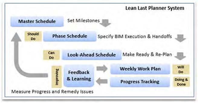
3.3.2 Last Planner System
The Last Planner System can manage the delivery process and improve team effectiveness through collaborative planning and communication. BIM development has a supporting swim lane to the overall project execution activities.
The five elements of the Last Planner® include:
- Master Scheduling (setting milestones and strategy; identification of long lead items);
- Phase "Pull" planning (specify handoffs; identify operational conflicts);
- Make Work Ready Planning (look ahead planning to ensure that work is made ready for installation;
- Re-planning as necessary; identification of Constraints affecting the planned work);
- Regular Work Planning (reliable commitments to perform work in a certain manner and a certain sequence); Learning (measuring percent plan complete (PPC), root cause analysis of reasons for not meeting PPC, and developing and implementing lessons learned).
2 Level of Development – First developed by Graphisoft, VICO/Trimble and adopted as an industry best practice by the AIA, and standardized into a
specification by AGC 2013. Adopted by the National BIM Standard (NBIMS)
3 Lean Institute and Lean Construction Institute
4 Bim Forum.org
5 Level of Detail and “Grade” are used in the UK BIM Specification
6 National Institute of Building Sciences, NIBS
7 IFC – an open non-proprietary exchange for BIM
4 - Lean/BIM Project Execution
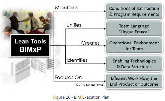
Lean and BIM are industry initiatives that mutually enable DCAMM’s project delivery strategy. Lean tools provide a structure for team collaboration and BIM the development and sharing of information.
4.1 DCAMM Project Collaboration Conferences “A” and “S”
The equivalents of Lean Value Definitions, Pull-Planning, and BIM Use experience is necessary for BIMxP development. Participants may not explicitly or formally invoke Lean tools and practices; however, Lean represents structured “common sense” best practices with some additional terminology to identify specific approaches and tools.
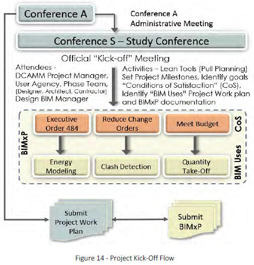
4.1.1 Collaboration Conference “S”
As soon as possible after the contract award, the Design BIM Manager and Project Team Manager will schedule with DCAMM the kick-off meeting to identify the project Conditions of Satisfaction (CoS), goals, and milestones. The BIM Manager will be present to align BIM Uses to the CoS for BIM Execution Plan (BIMxP) development. A lean facilitator is recommended to help wring out non-value-add activities and to re-enforce DCAMM’s interest in Lean principles.
Team members, consultants, BIM Managers from all participating entities, and discipline BIM Coordinators will attend the meetings and participate in the Lean value mapping. Project Pull Planning will be used to identify the project CoS. The DCAMM BIM Manager will work with the other team members to align BIM Uses in the BIMxP with the CoS.

- Lean and BIM
- Project teams from multiple firms have different understandings of how BIM is developed, executed, and shared during a project.
- It is in the best interests of the project that a comprehensive and unified strategy for team collaboration, and BIM development be created at project inception.
- DCAMM has developed its BIM tools and Lean project requirements to support a team conversation leading to a comprehensive project strategy.
How the BIM Uses are executed supports the project pull plan. A BIM swim lane will be added to the base of the Project Pull showing how BIM will support specific project actions.
During the project, progress workshops will be scheduled to determine the following: resolution of the areas and adjacencies; building components and quality; the construction cost; and adherence to the schedule. Checklists are included at the completion of each phase to aid the Designer, the User Agency and DCAMM staff in the review process.
Additionally, the DCAMM BIM Manager will document the model progression, element level of development (LOD), collaboration protocols, modeling environment, model review and approval conventions using the DCAMM BIMxP template.
4.2 BIMxP Submission
A description of how the modeling activities will be met is required from the Design BIM Manager and subsequently, from the Construction BIM Manager. The Design BIMxP shall identify how the design team will develop the WIP models, be responsible for BIM Use execution, provide for model reviews in the Progress Meetings and Global Workshops, and federate models into the Design Intent/Coordination model.
The BIMxP will identify their proposed in-house or outsourcing plan, and all software programs that will be used to satisfy the modeling goals, model analysis, decision support and reviews. Within the agreed upon submission schedule, the BIMxP will be submitted to DCAMM for review and approval.
The Design BIM Manager will continue to update the BIMxP during project execution. The Design BIM Manager will work with the project and discipline-modeling teams to assure that BIM execution supports the ongoing project mapping and schedule.
5 - The BIM Execution Plan (BIMXP)
The BIMxP template is the primary means of developing and documenting the unified team strategy for BIM collaboration and development. It documents the BIM infrastructure for model sharing and collaboration. The BIM Execution Plan:
- Establishes a basis for communication between BIM parties.
- Develops clear guidelines for internal and external collaborative working which maintain the integrity of electronic data.
- Documents project infrastructure, (software, hardware, server) suppliers, and hosts BIM.
- Documents contacts, BIM roles and responsibilities.
- Documents the Meeting Schedule for BIM execution, model submission and review.
- Identifies the process flow for BIM Uses, and shows the connection to project milestones, model submissions, model progression and LOD. Lean Pull Planning and Value Stream Mapping will facilitate this activity.
- Defines information exchanges, shared access, and model federation.
- Documents model access and security protocols, model integrity and data safety plan
- Establishes measureable goals for BIM success and team execution
5.1 Bim Execution Plan Template
The DCAMM BIMxP template is a semi-automated spreadsheet with pull-down menus that documents team and project information (Sections 1, 2); Lean Conditions of Satisfaction aligned to BIM Uses in Sections 3, 4, and 5. Section 6 is the template for clash detection reporting.
5.1.1 BIMxP Tools
Introduction and Standards
- General Project Information - Contacts and responsibilities, team members
- Collaboration Procedures - Meeting schedule, collaboration procedures, software, versions
- Lean Conditions of Satisfaction (BIM goals) - BIM Conditions of Satisfaction section aligned to BIM activities
- BIM Use Matrix - The BIM Uses (Appendix A.) are identified and prioritized for project execution
- Model Element Progression Worksheet - The Upper Section documents BIM Use execution across the project phases. The lower section defines the LOD of the required building elements (in template) for review by the DCAMM project manager and BIM manager at the end of project phases. This section uses UniFormat for elements.
- Two Tabs for Clash Detection Matrix and Report - DCAMM has provided a structure for documenting and reporting clash detection and coordination activities.
- Look Up Tables (Not for Modification)
BIM Use Categores
- Existing Conditions
- Systems Authoring
- Analysis and Reporting
- Sustainability, LEED, Energy
- Design Constructability Reviews
- Documentation and Specifications
- Commissioning, Handover
- Facilities, Operations
- Data Assurance
5.1.2 BIMxP Management and Updates
The BIMxP will stay current with project BIM requirements, LOD development, new stakeholders’ contributions, meeting schedules or new tasks. The Design or Constructor BIM Manager will be responsible for BIMxP updates. DCAMM will review the BIMxP BIM execution and LOD development at the BIM milestone reviews (Section 5. Model Progression). Any issues or discrepancies in BIM Use execution, modeling requirements and structure should be brought to the attention of DCAMM and resolved in the BIMxP for the project.
5.2 Model Progression Matrix
The Model Progression Matrix is a Microsoft Office Excel® tab with two main sections. The upper section is used to list the BIM Uses for the project, and identify when the BIM Use will be executed. A BIM Use may be executed more than once and across project phases.
The lower section of the matrix identifies the required DCAMM model elements, ownership, and the LOD progression to be tracked during the project phases. Not all objects will be tracked.
5.3 Model Collaboration Environment
There are numerous meetings and communications to be documented and managed on projects. The prime will provide a team collaboration site for general project communication. The PM, DCAMM BIM Manager and Design BIM Manager will determine the schedule for project meetings when BIM will be used.
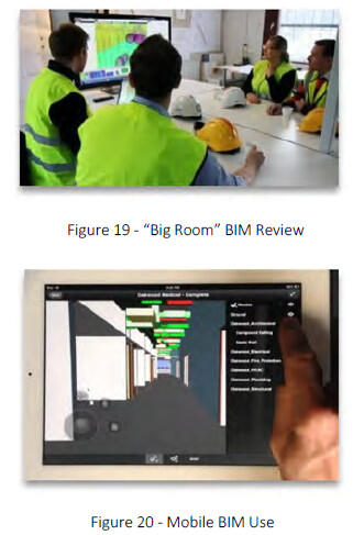
The Design BIM Manager shall provide a team (physical or virtual) “Big Room”, and model (digital) environment for reviews. If a CM is part of the project, then DCAMM may require the CM to provide a Big Room and server environment for the project. The procedures are to be documented in the BIMxP template.
- Collaboration Meetings – “Big Room”: A space for team meetings with virtual participation capability and BIM review capability. It includes equipment necessary for BIMeview and modification. Specifications for the BIM collaboration “Big Room” and equipment shall be provided to DCAMM for approval with the BIMxP. At or around the time the CM is retained, this responsibility will transfer to the Contractor and its BIM Manager.
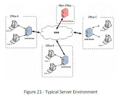
- Virtual Collaboration: DCAMM anticipates using mobile collaboration (BIM 360 or similar) in the field. Once this has been settled and implemented, the project team will work with DCAMM to identify project specific in-field BIM use requirements. Tools will then be documented in the BIMxP template.
- BIM Server: A BIM Server or shared model site is preferred over document management only sites. Procedures for model sharing, data development, document management, and secure model access, shall be documented in the BIMxP.
- Training and Team Orientation: Appropriate training and instruction materials (manuals, training videos,) shall be model site. Training will assure team members can function effectively in a collaborative manner, with the necessary access to model data to perform their roles on the project. A model viewer and training shall be provided for nontechnical viewing of the model. Navisworks, or other viewers used will be documented in the BIMxP. The DCAMM project manager and the DCAMM BIM Manager will have access to the model for review.
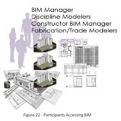
6 - BIM Team Members
The Design BIM Manager, the consultants, the constructor or CM BIM Manager, the fabricators and trades may all develop, manage, or use BIM during a project. Therefore, all teams shall have the appropriate level of BIM expertise to execute their respective project scopes of work (SOW).
6.1 The Design BIM Manager’s Role
The Design BIM Manager provides overall BIM direction, continuity in model development, and quality control, per the BIMxP. This BIM Manager’s tasks include:
- Reports directly to the project architect
- Creates the BIMxP for the project
- Oversees development and publication of model configurations and supports seamless integration of the WIP models and project data
- Ensures software is installed, operating properly at the application level, and is version-synchronized
- Facilitates design clash detection of WIP models and the design intent model for meetings; provides detection reports, and the clash and resolution of all hard and soft collisions
- Ensures that BIMs are used appropriately to test design requirements and criteria for functionality
- Assumes responsibility for the proper classification of all spaces and equipment
- Determines the project BIM geo-reference point(s), and assures ALL technical discipline models are properly referenced
- Assures that the design deliverables specified in the contract are provided in accordance with the formats specified at design coordination and project handover
- Assures proper BIM-derived 2D information and drawings for paper printing or publishing conforms to NCS (and DCAMM CAD standards where applicable)
- Ensures construction documents are produced from a fully coordinated design intent model
- Ensures the transfer of BIM management responsibilities to the constructor team
6.2 The Constructor’s BIM Manager Role
The design team’s model will be shared with the constructor. “Constructor” includes the traditionally designated “General Contractor (GC)” or Construction manager or CM at Risk (CM@Risk) as well as subcontractors in their capacities as both builders and influencers of design execution. BIM responsibilities of the Constructor BIM Manager include:
- Maintaining the BIM and integrating appropriate information developed during the construction phase, managing model handover from Design BIM Manager
- Developing the BIM Coordination Room (or “BIG room”)8 specfication for DCAMM approval
- Ensuring that the Construction Team has necessary hardware and BIM software properly installed and accessible for project use
- Coordinating sub-contractor BIM use
- Facilitating clash detection and resolution of hard and soft collision reports using the DCAMM Clash Report template
- Coordinating construction sequencing and scheduling activities, and assuring they are integrated with the Construction BIM
- Communicating with the Design Team, and coordinating the data extraction sets required by the construction trades, and ensuring that these requests are met
- Coordinating with the Design Team to facilitate documentation of field design changes and timely update of the Record BIM
- Working with Lead Fabrication Modelers prior to approval and installation, to integrate 3D fabrication models with the updated design model to ensure design intent
- Working with the Design Team BIM Manager to coordinate model commissioning and data handover
6.2.1 The Constructor BIM Manager Coordination Role
In addition to the project scope of work requirements, the constructor shall provide consulting, leadership, oversight, and technical capability to support DCAMM’s BIM objectives on projects. The CM shall provide expertise and resources to maximize the effectiveness of BIM and related technologies for program management, project and construction management, and other analytical services to improve quality, reduce costs, and gain operational efficiencies on DCAMM projects. As regards BIM, the constructor shall:
- Facilitate development of the BIMxP, review BIM Use strategies defined by the team, and monitor execution
- Provide oversight of the model progression, standards and data development, and BIM Use scheduled execution developed in the BIMxP
- Coordinate BIM reviews with DCAMM personnel for decision support
- Work with Design team and contractor to maximize BIM sharing and data re-use
- Provide additional BIM capabilities if needed to minimize project risk
6.2.2 Model Handover - Design BIM Manager to the Construction BIM Manager
The BIM Managers shall facilitate model handover between design and construction. At handover, the Constructor BIM Manager will assume management of the following duties:
- Ensuring compliance with the DCAMM BIMxP template and updates the BIMxP Model Progression schedule during construction
- Facilitating software and protocols training

- Coordinating the set up of a shared file server: this shall include a web portal, permissions, transfer protocols, software versioning, and mechanisms for BIM use
- Facilitating coordination meetings
- Facilitating BIM meetings with trades
- Interfacing with DCAMM BIM Manager for model review and handover
- Coordinating BIM file exchange and archiving milestone submittals
- Assuring that COBie17F or asset information is provided at milestone submittals Coordinating updates of as-constructed conditions in the Record/As-Built Model deliverable
- Coordinating with the Design Team and Commissioning Agent to assure COBie information is accurate and complete.
6.3 Additional BIM Team Members
The design and constructor BIM Managers will coordinate their teams. The design BIM Manager works with the discipline modelers WIP models. The Constructor oversees the fabrication and trade modelers.
6.3.1 Discipline BIM Modelers
All major disciplines shall assign an individual to the role of BIM Discipline Coordinator. These individuals shall have the relevant BIM experience for project responsibilities, which include:
- Coordinate discipline BIM development, standards, data requirements, as necessary, with the Design BIM Manager
- Direct the discipline BIM team
- Coordinate clash detection and resolution, and federation of the discipline model with the Design Intent model with the Design BIM Manager
- Coordinate specific discipline activities in the BIMxP
- Coordinates information needed by DCAMM New CAMIS (Tririga) from trade and technical disciplines
6.3.2 Trade/Fabrication BIM Coordinators
- All major trades shall assign a BIM Coordinator to manage the sub-trade model development, sharing, and use with the CM BIM Manager.
- Develop detailed models for Shop Drawings
- Support pre-fabrication and fabrication requirements
- Provide data in DCAMM standards or COBie as required
- Manage scheduled model updates and exchanges
- Participate in clash detection and resolution activities
- Coordinate internal BIM training
- Coordinating clash detection and resolution activities
7 - Modeling Requirements
The model is a contract requirement for use during project execution by the project team, and post project by DCAMM or User Agency personnel. The model environment should be documented in the BIMxP so that others may view and access the model during project execution, and understand its structure for use post project.
Abbreviations, naming conventions shall conform to the requirements in the DCAMM CAD Manual.
7.1 Model Framework
The model shall conform to “best practice” modeling procedures, data standards, naming conventions, and LOD required meeting project requirements. BIM authoring tools and non-BIM applications used on the project will be documented in the BIMxP. DCAMM will approve applications used on the project.
The Design or Constructor BIM Manager will test applications that are proposed for use on the project before the application is submitted to DCAMM for approval. This testing will be documented in the BIMxP.
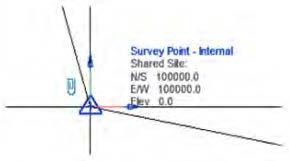
7.2 Model Geo-Reference
DCAMM requires that models be correctly placed in 3D space. The model shall use the real-world coordinate system for the building grid. The model shall use true height above project datum.
The design BIM Manager shall establish the project shared coordinate system across all BIM data files to allow them to be referenced without modification. . Geo-referenced site plans and building models shall be in accordance with the Massachusetts State Plane Coordinate system.
BIM Authoring Software
DCAMM uses Autodesk Revit Suite for projects. Other applications require approval by DCAMM. Applications are documented in the BIMxP. Other applications might include:
- 3D CAD applications (AutoCAD, CADmep, CADduct, QuickPen, Civil 3D)
- BIM authoring applications (Revit Suite, ArchiCAD, Bentley BIM, Trimble Tekla Structures, SketchUp, Vico Office)
- BIM Programming applications (Affinity, Beck Technologies, Autodesk InfraWorks)
- Design coordination software (Navisworks, Solibri Model Checker, BIM 360)
- Cost modeling (Navisworks 2014, Modelogix, Vico, etc.)
- Scheduling Software (Synchro, Vico Office)
- Energy Modeling (Green Building Studio (GBStudio) , IES, Ecotect, LBNL EnergyPlus)
- Project management software (Prolog/Proliance, e-Builder, CMiC, Vico Back Office, Newforma, etc.)
- Data management software (EcoDomus PM, Solibri, etc.)
Revit workflow dictates that building models are created orthogonal to the screen and at zero elevation. The location of the building at real-world coordinates, true heights, and shared coordinate systems are established by the BIM Manager in the site model.
All models will share a common project origin established by the project team BIM Manager. Once established, spatial coordinates shall only be changed by mutual consent of the team and the DCAMM project manager, shall be recorded in the BIMxP, and promptly published to all team members. Once the design coordinate system is agreed upon, any model(s) of existing buildings relevant to the project shall be converted into the coordinate system used for each designed building.
7.2.1 Points of Reference – 3D Building Grid
Depending upon the size of the project, the prime BIM Manager shall provide a 3D grid for incorporation into the spatial coordination model. This will provide the viewer with a quick point of reference when navigating through the model. This grid will be part of the As-Built deliverable to DCAMM.
7.2.2 North Arrows
Both true north and project north shall be on construction sheets as required for documentation.
7.2.3 Fonts
Standard Autodesk and Microsoft fonts shall be used on DCAMM projects.
7.2.4 Modeling Tolerances
Model elements are to be modeled within one-eighth inch (1/8”) of actual location (3mm). The automated dimension strings in the BIM software should be used. Dimensions in derived 2D drawings should sum correctly within tolerances specified in the BIMxP. Dimension strings shall retain their associativity. If laser layouts (total station) are used in the field or pre-fabrication is required, then the modeling teams will review the tolerances required in those areas and for that building system component with the CM or trades. Results of such a review and any adjustments affecting current and future modeling shall be documented in the BIMxP.
7.3 BIM Objects, Elements, and Components
Use BIM authoring software element libraries when creating model objects. Model objects shall contain parts and components as opposed to simple 3D Geometry. For example, BIMs shall be composed of the software’s model elements for representing walls, doors, windows, railings, stairs, and furniture, rather than geometric lines, arcs, and vertices. All objects and components will be modeled or created using the tool in the software prescribed, or created for the purpose. For example, the wall tool is used to model walls, a window object to model a window. If a new object is created then it must be designated as the real world element it represents, having the proper class or family data attributes for the project and that object type.
Object, component, and element attribute data shall be fully parametric so that equipment, fixtures, and building elements information can be generated from the model for quantity take-offs, finish, door and other necessary construction schedules.
When represented as architectural elements using the designated tools provided in the authoring software, the information associated with these elements will be properly updated, reported, and available for export.
Generic Objects: BIM applications include generic representations of building products, assembled elements, and components of building systems.
Manufacturer’s Product Objects: Objects and elements acquired from manufacturers often have more information or geometric detail than is necessary to keep in the BIM. The BIM Manager shall determine if the manufacturer object is appropriate for the model. The object should retain its overall dimensions and critical components. Embedded performance data shall be retained for analysis and specification purposes.
7.3.1 Custom Created Model Elements
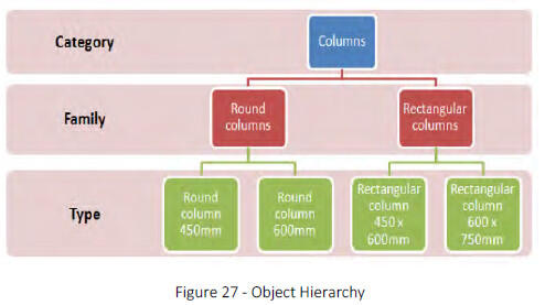
Teams may create BIM objects and elements utilizing the appropriate BIM authoring tool templates and procedures. These must be assigned to the correct category, family, type, and/or sub-type according to the authoring software’s best practices, and they must carry the required and desired attribute data consistent with DCAMM standards. Object creation management, classification, and attribute inclusion and mapping (sometimes called “library management,” “family management,” “sub-type management”) must be done in standardized ways consistent with BIMxP requirements, following best practices for the BIM authoring tool. Objects created by scripting, or that incorporate custom scripting in the BIM authoring tool’s environment, shall be thoroughly documented and included as part of the work product being delivered to DCAMM. Live, editable instances of BIM objects so created must accompany the BIM deliverable so that all Use identified in the BIMxP continue to be supported by the model after model handover to DCAMM. Support for correct IFC output shall be maintained by custom objects.
7.3.2 Object Element Attribute Data Reliability
Attribute data are developed throughout the project lifecycle. Information about the elements in a BIM becomes increasingly important as the BIM develops. Similarly, the importance of information about where the data came from, and when, increases. Accordingly, objects that have time-sensitive data in their attribute fields should be documented in the lower section of the Model Progression Matrix with the responsible party and the current LOD by phase. Data attributes at:
- LOD 200 are generic and suitable for early performance analysis and design options,
- LOD 300 are suitable for performance requirements, estimating and procurement;
- LOD 400 at project turnover defines the information on the installed product or building element; and
- bid Documents are generally LOD 300.
7.3.3 Level of Development Use
Agreed upon objects and elements shall carry the LOD level for reporting at model submission milestones. If the object does not have the LOD attribute, then the team will add the attribute to objects used in the model.
7.3.4 Master Attributes
Within a Revit model, attributes are assigned and data developed for specific objects and elements. A list of schedule data will be developed as part of the BIMxP model progression. If COBie BIM Use is specified, then COBie requirements will be used.
7.4 Wall Type Naming Conventions
Wall types are “in place” elements in Revit. They are defined, utilized and stored in a Revit project file or Revit template.
Wall type naming conventions allow for easy identification in the type selector menu. These names cannot be driven from the wall type parameters. This means that some information about the wall type will be duplicated.
DCAMM recommends the following naming structure and industry abbreviations for materials. On final models, wall types for fire rated walls and bearing walls will be graphically represented.
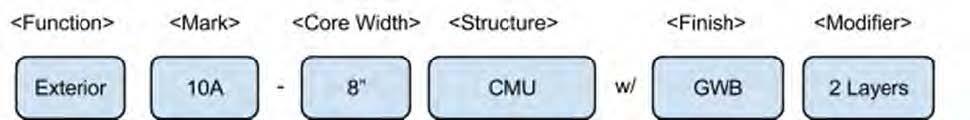
The recommended wall type naming consists of identifying the primary function followed by the core thickness, structure and finish. Add additional parameter information for Fire rating as needed. The type selector will automatically sort alphabetically. This naming convention keeps similar types together and easy to locate.
7.5 Space Naming, Room Numbering, and Coding
Areas of four square feet or greater shall be tracked and identified by name. Each space shall include the following attributes to be maintained throughout the Design and Construction BIM models:
- Building – Name, Number Code & Location
- Wing
- Floor/Level
- Department
- Sub-department
- Space Name—English Name & Abbreviation
- Room Number—DCAMM Way finding Room Number
- Space Function—OmniClass Table 13 (Room Description)
- Room Number—Construction Document Number (used on large complex projects for builder use)
- Unique Space Number—GUID
- Space Measurement—Net Square Footage (NSF), Department Net Square Footage (DNSF), Department Gross Square Footage (DGSF), and Building Gross Square Footage (BGSF)
- Zones – zones may be made up of rooms (where BIM wall, door and ceiling elements serve as boundaries), or physically unbounded spaces designating a specific function that are delineated by 2D or 3D lines. Examples include HVAC, organizational divisions such as workgroups or departments, or a space designated as an elevator lobby that is contiguous with a corridor or designated reception area.
Whenever calculating the Building Gross Area, Departmental Gross Area, or Net Assignable Area, the Designer shall adhere to the following specific methods of area calculation:
Building Gross Area: The floor area of a building for all levels that are totally enclosed within the building envelope, including basements, mezzanines, or penthouses. To compute Building Gross Area, measure to the outside face of exterior walls, disregarding cornices, pilasters, and buttresses, that extend beyond the wall face. The Building Gross Area of basement space includes the area measured to the outside face of basement foundation walls.
Departmental Gross Area: The net assignable areas and required secondary circulation assigned to an occupant group or department. To compute the Departmental Gross Area, measure to the inside finished surface of the exterior building walls, to the finished surface of the walls surrounding major vertical penetrations and building core and service areas, and to the center of the walls dividing the space from adjoining Departmental Gross Areas.
Net Assignable Area: The area required to accommodate a function, equipment, occupant, or occupant group. Net Assignable Area includes interior walls, building columns, and projections. Net Assignable Area excludes exterior walls, major vertical penetrations, building core and service areas, primary circulation, and secondary circulation. To compute the Net Assignable Area, measure to the inside surface of the exterior building walls, to the finished surface of walls surrounding major vertical penetrations, building core areas, and service areas, and to the center of partitions separating the Net Assignable Area from adjoining Net Assignable Areas and from secondary circulation space.
FICM: (Facilities Inventory and Classification Manual) space designations, space coding, and classification standards shall be used on projects in the post-secondary education domains.9 When used correctly, FICM designations enable correct reporting of space uses for university and governmental purposes, and include appropriate granularity and roll-up support.
7.6 View Naming and Model Navigation
A view-naming standard shall be documented in the BIMxP for model navigation. This standard can be limited to drafting views and sheet views in the BIMxP, and provided to the DCAMM project manager.
- Level names are spelled out, as they need to appear in a room schedule, as well as how they will appear in sections and elevations. Do not pad the level number with leading zeros.
- Views shall not be named in order to make them sort or group more logically in the Project Browser as the grouping and filtering settings take care of that automatically (i.e., the prefixing of level names by sequential numbers).
- View names shall be written in UPPERCASE.
- Creation of temporary working views is encouraged.
9 See National Center for Educational Statistics for an explanation of FICM and its extensibility to accommodate “…. extension codes to distinguish control over classroom areas…”
8 - BIM Data Infrastructure
DCAMM and industry data standards are necessary to achieve a consistent BIM deliverable across multiple projects. These standards include model metadata, model structure, object and element attributes, naming conventions, and LOD. The DCAMM BIM Manager must approve deviations from these standards in writing before proceeding with any work that contradicts or implies modification of these standards.
8.1 Data Standards for DCAMM BIM
DCAMM currently uses UniFormat and MasterFormat in its projects. UniFormat is used in the BIMxP. As part of the move to BIM, DCAMM is transitioning to the Construction Specification Institute (CSI) OmniClass™ Construction Classification System (OCCS).10 The OmniClass Tables are part of the National BIM Standard (NBIMS). Two tables currently used:
- Uniformat - 2010
- MasterFormat Table 31 – Phases
- Table 11 – Construction Entities by Function
- Table 13 – Spaces by Function - Space tracking is essential for DCAMM to review program compliance and manage its building portfolio. In BIM, OmniClass Table 13 (number and name classifiers) are to be used for model space attributes. In projects for post-secondary educational facilities, FICM space classifications shall be used so that required space use reports can be properly generated.11
The BIM Execution Plan (BIMxP) Template, Section 5 uses Table 31- Phases. The phases are listed below with a cross-reference to traditional design and construction project phasing.
| Table 31 | OmniClass Phase Name | Traditional Phasing |
|---|---|---|
| 31-10 00 00 | Inception Phase | Project Planning |
| 31-20 00 00 | Conceptualization Phase | Schematic Design |
| 31-30 00 00 | Criteria Definition Phase | Design Development |
| 31-40 00 00 | Design Phase | Design Development |
| 31-50 00 00 | Coordination Phase | Construction Documentation |
| 31-60 00 00 | Implementation Phase | Construction |
| 31-70 00 00 | Handover Phase | Commissioning, Close-out |
| 31-80 00 00 | Operations Phase | Facilities Management, |
| 31-90 00 00 | Closure Phase | Closure, Decommissioning |
8.1.1 UniFormat Transition
DCAMM will identify whether UniFormat, OmniClass, FICM, or a specific DCAMM standard will be used for cost estimating, building assessment projects, or other work products. The use of all standards will be identified in the BIMxP for the project.
- Table 41 – Materials and Table 49 – Properties
8.1.2 Model Data Requirements
The model carries data within a hierarchy of model development. Each discipline, federated, and design model carries its DCAMM project metadata.
- Project ID – DCAMM Construction Project Number
- Building ID – Provided by DCAMM
- Building Type – OmniClass Table 11
- Project Name – Provided by DCAMM
8.1.3 DCAMM Equipment and Room Data Requirements
DCAMM has identified data and attribute requirements for buildings, rooms, spaces and equipment required during the project and at model turnover.
- The design team will use the - Data Verification and Collection Form Set 2-26-14.xlsx to identify the elements in the project that are requirements at handover and document the LOD of these objects during design and construction.
- The BIM Manager will add the appropriate attribute fields of objects to support the DCAMM requirements.
8.1.4 Data Organization – Recommended Work in Progress and Publication Views
Documented model organization is important for model reviewers. The following are recommendations for project model structure. This recommended structure, or another one specified by DCAMM, is to be documented as part of the BIM procedures in the BIMxP.
The Project Browser in Revit provides an organizational structure to the views and components within the BIM environment. The following rules are defined to sort WIP views from Publication views.
- View folders shall be grouped by Family and Type and sorted by Associated Level in ascending order.
- The views shall be filtered by Sheet Name, which should be Equal to a value of None. View section will then show only views not allocated to a drawing sheet.
Sheet folders shall be grouped by Sheet Number using 1 Leading Character and sorted by Sheet Number in Ascending order
10 All OmniClass tables, and education options are available at: www.omniclass.org
11 FICM standards allow for extensions to its designations. Omniclass Table 13 designations may therefore be used coded into FICM designations, or carried by BIM space elements as a separate data field
9 -Drawing Requirements for Paper Printing and Publishing
This section provides additional graphic standards for BIM based construction-drawing documentation and model submissions.
The BIM documentation should conform to the DCAMM CAD conventions for file naming, discipline abbreviations and paper deliverables.
The DCAMM Project Manager and DCAMM BIM Manager must approve deviations from these requirements in writing before proceeding with the work.
The Design BIM Manager shall attend a mandatory project initiation meeting with DCAMM to review the BIM standards, CoS selection and BIMxP development, and project submission requirements.
9.1 Precedence of BIM Design Materials
DCAMM’s objective is for the Design Model to function as the primary means of communicating the project’s design intent. However, DCAMM recognizes that in limited situations, two-dimensional drawings (that may or may not be derived directly from the Design Model), as well as other subsidiary three-dimensional models (or model elements) may co-exist or supplement the Design Intent Model as the primary means of communicating intent. Thus, there may be situations where the Design Model is in conflict with these materials.
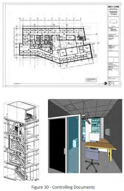
9.2 Controlling Documents
The controlling documents for a project using BIM as a primary means of Study, Schematic Design, Design Development, and Construction will be the applicable contract documents between DCAMM and its Designer and Constructor. Typically, such contract documents will include, by specific reference, requirements tied to the various portions of the contract documents. If this BIM Guide is in conflict with contract documents the contract documents shall take precedence.
9.3 Electronic Deliverables
Construction drawings (CDs) are required submissions on projects and shall conform to the DCAMM CAD standards where applicable.
In a BIM-based project, these drawings (plans, sections, elevations, 3D details, axonometric and/or perspective views) shall be derived from the model. Drawings may be published during project development in native formats, .rvt, web views, .dwf, .nwd, .pdf, and .dwg.
Electronic deliverables includes studies, data, or graphics, and may include models and drawings. Final submissions that do not include all files and documentation are incomplete. DCAMM strongly emphasizes the importance of final record drawings. These models and drawings will be used in facility management by DCAMM and by client Facilities Management departments. State buildings typically have significant changes in their configuration over their life span. Accurate record models and drawings are of vital importance in these building management and alteration processes.
9.4 Drawing Validation
- Sheets from the BIM shall be published to DWF (preferred), PDF or other non-editable format, where they can be checked, approved, issued and archived as traditional documents.
- Validation of the BIM data prior to sharing shall check that:
- All drawing sheets and extraneous views shall be removed from the BIM
- Model file has been audited, purged and compressed;
- File format and naming conventions conform to project Data Exchange protocols,
- Data segregation conforms to the agreed project BIM methodology,
- Model files are up-to-date, containing all users‟ local modifications,
- Model files are detached from central file,
- Any linked reference files have been removed and any other associated data required to load the model file is made available,
- Model is correctly assembled through visual inspection,
- Any changes since the last issue are communicated to the project team.
9.5 Designer Record Drawings Turnover
- Record Drawings shall be submitted as follows: Three required sets: one to DCAMM Distribution Manager and two to the client agency.
- PDF files of dated/Stamped Record Drawings.
- AutoCAD files (.dwg format) of record drawings.
- As-Builts Sketches shall be submitted as follows: PDF files of dated/Stamped Record Drawings on the media specified on the Media specified in section 2.5.2 (May be included on CD with Record Drawings)
9.5.1 A/E Seal on Drawings
Every sheet, including the title sheet, must include the applicable stamp of a Registered Professional Engineer and/or Architect licensed in the Commonwealth of Massachusetts, with the Engineer or Architect of Record’s (Prime Consultant and all Sub-Consultants) signature over the seal. Both the seal and signature must be readable when reproduced. DCAMM is in the process of addressing digital signatures. Any request regarding clarification or approval of digital signatures should be made by the Designer’s BIM Manager to the DCAMM project manager.
9.5.2 File Naming Format
All model deliverables shall be saved and delivered in their native format (i.e., .rvt for Revit, .pln for ArchiCAD, etc.), in IFC format, .dwg and .dwf formats; in .nwd, .nwf, and .nwc as required; and placed on the required FTP or project website (with appropriate securities and versioning controls) for the entire project team to review during the project and per DCAMM submission requirements at handover. The naming of project documentation files (for examples, .TIF, .PNG, .PDF, and .DOCX, .MOV, etc.) shall include the following information and sequence.
9.5.3 Drawing Layouts & Title blocks
The DCAMM CAD (dwg) Title Block and Information shall be adapted for BIM use by the Design BIM Manager. See DCAMM CAD Standards Manual
- Size/Margins: The outside dimensions of both preliminary and final working drawings must be either 24 x 36 inches, 30 x 42 inches, or 36 x 48 inches. The Project Manager will designate the appropriate drawing size. Within these dimensions, drawings must have a ½ -inch border on the top, bottom, and right sides, and a 1-inch border on the left side.
- Title Sheet: A title sheet must accompany each set of drawings, unless DCAMM waives this requirement. The title sheet should contain a proper and accurate indexed list of applicable drawings.
- Sheet Identification, Sequence, and Index: All drawing sets must include a complete index on the cover sheet that lists individual sheet titles and numbers for all disciplines in the set. This naming convention shall follow the National CAD Standards (NCS).
- Legends, graphic symbols, and general notes must appear on the first sheet of each discipline’s set of drawings.
- Discipline sheet sequencing shall follow the NCS standard. National CAD Standards (NCS).
- Key Plan: A key plan must be shown in the lower right-hand corner of all sheets having floor plans, elevations and building sections. The plan must identify the area depicted on the sheet. The key plan orientation must be the same as the floor plan orientation on the same sheet.
- Plan Views: All drawings in a set must be oriented in the same direction.
- Scales on Drawing Sheets: The scale of the drawings must be shown on each plan, elevation, section and detail. Each drawing must include graphic scales. The following designated scales are required as a minimum:
- Floor Plans 1/8"=1'0"
- Mechanical/Toilet Rooms 1/4"=1'0"
- Elevations 1/8"=1'0"
- Building Sections 1/8"=1'0"
- Refl. Ceiling Plans 1/8"=1'0"
- Wall Sections 3/8", 1/2" or 3/4=1'0"
- Roof Plans 1/16” or 1/8"=1'0" Site/Civil Plans 1” = 20’ or 40’
- Graphic scales must be included on all drawings.
- Layer Conventions – DCAMM utilizes the NCS v5 layer standards with the following exception: Layers used by the design team should be submitted as part of the BIMxP.
9.5.4 Horizontal Construction:
- DCAMM currently has separate AutoCAD layering standards for site/civil drawings. These layers are listed within the drawing named “DCAMM-SITE-CIVIL-LAYERS.dwg”. Layers created that have additions, deletions or enhancements should be named with the appropriate prefix added to DCAMM’s existing site/civil layering standards. Separate text layers must also be created for any new text added to the drawing.
- The following is a list of prefixes:
- Y – survey information
- ASB – As Built information
- DES – design or proposed information
- DEMO – demolished information
- ABD – abandoned information
- Existing information uses DCAMM’s Site/Civil/Utility layering standards without a prefix
- Project Limits: Each Project will require a layer called “BIM-PROJECT-LIMITS-L”, which will be drawn around all project work areas.
- Site/Civil Drawing Coordinate System: AutoCAD site/civil basemaps supplied by DCAMM are created in relation to its geographic location. The insertion base point (0, 0) can be related to a control network of other nearby sites. The horizontal control network of the basemap uses the Massachusetts Mainland State Plane Coordinate System (Zone 2001), as referenced to the North American Datum of 1983 (NAD83). The vertical component of the network is referenced to the National Geodetic Vertical Datum of 1988 (NAVD88). Site/Civil basemaps should NEVER be moved or rotated in a manner that removes the drawing from the control network. If the orientation of the basemap needs to be changed, the use of Paper Space with a User Coordinate System should be used to rotate the perspective of the basemaps. Decimal units are used for all DCAMM site/civil/utility basemaps.
- Utility Line Data: Utility lines SHOULD NOT be broken for the purpose of annotation. Utility lines should run continuously from structure to structure. Lines should be annotated above or below the line.
- North Arrow: An arrow indicating north must be shown at the upper left-hand side of the drawing of all floor plans, including site/civil, architectural, structural, plumbing, fire protection, mechanical and electrical drawings.
- Clearances: Mechanical Room drawings must graphically show access door swings on A/C equipment and coil filter removal clearances. A model view shall be provided to further identify access and maintenance clearance. Consideration must be given not only to the space required to perform maintenance, but also to the space required to gain access to the maintenance space with maintenance equipment and tools.
- Building Area & Volume: Drawings must show accurate building areas and volumes to foster accurate comparisons of the project areas and volumes compatible with construction industry standards. DCAMM will review the criteria to be used. BIM volumes, color coded with areas/volumes reported must be provided for all projects, and the building areas must be recorded as a schedule on the Architectural Drawings.
9.5.5 Standard Details and Finishes
A different partition type is to be created for each type of wall used in the project with each type constructed in 3-dimensional form.
9.5.6 Font and Lettering Size
Lettering: A minimum letter size of 1/8 inch for notes and 1/4 inch for titles must be used to allow them to be reproduced in one-half of their size. System fonts are to be used. Ariel, Callibri, New Times Roman
9.5.7 Text in Files
It is recommended that the following text assignments be used on DCAMM projects
| Text heigh (mm) Plotted full size | Line Weight Allocation | Usage |
|---|---|---|
| 1.8 | 2 | General text, dimensions, notes - used on A3 and A4 size drawings |
| 2.5 | 3 | General text, dimensions |
| 3.5 | 4 | Sub-headings |
| 3.5 | 5 | General text, dimensions, notes - A0 drawings |
| 5.0 | 7 | Normal titles, dreawing numbers |
| 7.0 | 8 | Major titles |
9.5.8 Line Styles and Line Weights
The internal software BIM Line Style defaults shall be used instead of the NCS and MP Linetype definitions. The A/E has the discretion and responsibility to edit the default line weight values of the BIM software so printed documents reflect the graphic intent of NCS and MP standards.
9.5.9 MEP Details (2D)
2D details from BIM MEP software do not always produce traditional component construction representations. Tagged definitions of the MEP object /elements shall be provided for clarity.
9.5.10 Project Documentation Schedules
Schedules will be derived from the model with additional information supplied by the project team member responsible for schedule data. Information will be organized in every schedule in a similar format with a heading, mark column, distinguishing characteristics12, and the notes column.
Numbers and note legends are recommended for schedules with duplication of note information in the note column, and to minimize the size of the schedule.
Heading
| Mark | Item Description | Distinguishing Features | Notes |
|---|---|---|---|
| 1,2 | |||
| 3 | |||
| 5 | |||
| 2, 3 | |||
| 4 |
Notes Legend:
- Note A
- Note B
- Note C
- Note D
- Note E
9.6 Discipline Model Drawings
Discipline model drawings are derived from the discipline models and the Design Intent Model. The information in the drawings and the building elements in the models align.
9.6.1 Architectural Drawings
These drawings should be identified as “A” drawings, dimensioned, and should include at least the following items:
- Plans of all spaces and views including floor, reflected ceiling, power/data/com and roof plans
- All fixed and specialty equipment
- All permanent fixtures
- Overall building elevations and building sections through the structure(s)
- Additional building sections as are needed to clearly illustrate the interior elevations
- Exterior and interior wall sections for all typical and all unique conditions showing construction and materials
- Detail drawings showing construction and materials
- Enlarged sections through the structure(s)
- Enlarged sections through stairways
- Enlarged plans and elevations of toilet rooms showing finishes, fixtures, casework and accessories
- Roof details including roof drainage outlets, flashing details, insulation, pitches of roof, chimneys, vent housing and the like; including all penetrations for vents, conduits, mechanical equipment, flues, pitch pockets and curb/wall details
- Partition schedule defining and detailing each interior partition type
- Room finish schedule documenting all finishes for each occupied and unoccupied interior space
- Door and window schedules defining and detailing all exterior and interior windows, doors and louvers
- Detail sections of windows, doors, permanent fixtures, finishes and similar basic elements of the structure(s), curtain walls, exterior walls and building system interfaces
- Casework details
- Signage schedule, plan and details
- Location of all mechanical and major electrical penetrations through walls and floors
- Mechanical conveyance equipment (e.g., elevators, escalators, conveyors, cranes, etc.)
- Plans and details of construction barriers
9.6.2 Structural Drawings
These drawings should be identified as “S” drawings and show at least the following items:
- The foundation construction, materials and details with the locations and sizes of all piles, caissons, spread footings, floating slabs, pressure injected footings as applicable
- Design soil bearing pressures shall be indicated on the foundation plans
- Complete foundation wall elevations showing location, dimensions, and grades for all floorings, steps and wall openings
- Elevations of top of structural slabs and finish floor elevations; complete dimensions for all openings, depressions, and changes in elevation of structural slabs; concrete floors relative to granolithic finish and concrete topping
- Complete dimensions and schedule for all lintels, beams, joists and columns
- Typical structural sections showing methods of connection, floor and roof deck selection, and the methods and locations of lateral bracing
- Complete dimensions and details for all members of the superstructure and for all expansion and construction joints
- Design live load for each roof and floor area
- Class and 28-day strength of concrete for each portion of the structure
- Boring plan, log of borings, date(s) borings were taken (bottom grades of footings, ground elevations, and slab and water elevations shall be plotted on boring schedule)
- Framing plans and schedules showing location, size and description of all columns, beams, joists and all other framing members
- Location of all major mechanical, plumbing and electrical penetrations through walls and floors
The Structural Drawings shall show all of the project’s design loads, and indicate allowable live loads for all of the various floor areas requiring different allowable live loads and snow load conditions including:
- Drift conditions
- Horizontal loads for wind and hurricane design conditions, if applicable
- Seismic loadings for earthquake conditions
- Concentrated loads and penetration resistance for special equipment
- Deflection loading
- All other applicable design loads
9.6.3 Plumbing Drawings
These drawings should be identified as “P” and show the following necessary items:
- A complete operative system of storm water and sanitary piping connecting to all drains, fixtures and equipment and extending to 5 feet from the outside of the building
- A complete system of cold and hot water distribution and re-circulation piping connecting to fixtures and equipment
- Insulating covering on all cold, hot and rain water piping and on other piping types as necessary
- Hot water storage heater, including insulation, controls, relief valves, thermometer, piping connections and appurtenances
- Backflow preventors in accordance with BWSC and State Plumbing Code
- Wall hydrants
- All interior sleeves, wall and floor plates, brackets, hangers, inserts, expansion sleeves, fixture supports and appurtenances
- Floor drains; special purpose drains to receive sanitary wastes
- Shower receptors and service sink receptors
- All plumbing fixtures
- Hot water circulating pumps and controls
- Grease interceptors and flow controls for kitchen sinks
- Traps and vents for all equipment
- Control valves
- Toilet room and shower room accessories
- Equipment and valve name tags and/or plates
- Water supply and drainage to air conditioning units and incinerating scrubber
- Shut-off valves on each water service to a group of fixtures
- Access panels for valves and cleanouts
- Concealed air chambers on each water supply to each fixture
- Water service connection
- Complete operating systems for distribution of all air, gas, or vacuum requirements
- System riser diagrams
- Gas and other ancillary systems
- Piping, filters, controls and accessories
- Temporary services
All piping shall be accurately sized and indicated on drawings and riser diagrams. Show directions of flow and pitch on piping. Utilize 3D views to show maintenance areas and pitch
9.6.4 Fire Protection Drawings
These drawing should be identified as “FP” and show the following items:
- Design layout and details
- Fire Protection Drawings shall provide the level of detail indicated in DCAMM Standard Specification
- The Consultant should also refer to Exhibit 3, Narrative Reports, Fire Protection
- Fire Protection riser diagram
9.6.5 Mechanical Drawings
These drawings should be identified as “HVAC” drawings and show Heating, Ventilation and Air Conditioning Systems including at least the following information:
- The location, within the mechanical spaces, and the type and size of the principle items of heating, ventilation and air conditioning, including fixtures and the necessary control systems and diagrammatic layouts of primary and modular distribution duct and piping systems for such equipment and fixtures, together with the necessary control systems
- Heat loss and heat gain calculations of the major heating, cooling and ventilating equipment shall be provided in a report describing the approach for meeting the minimum requirements of the Massachusetts Energy Code
- All directions of flow and pitch on piping, and direction of flow, volumes for duct systems shall be indicated. All ductwork shall be shown as double line
- Mechanical Room layouts - these drawings should including a Boiler and/or Equipment Room for: boilers to steam to HW converters; refrigeration machines; pumps - HW, CW, CT, expansion tanks; storage tanks; water service; all associated piping and accessories; louvers; flues, stack controls and instrumentation; equipment removal provisions; temperature control system elements, (e.g.: compressors, panels, etc.)
- Sections through congested spaces
- Air handling units - these drawings should include FA intakes and louvers; fans and drives; filters; HW and CW coils; controls; associated duct work
- Piping distribution systems - these drawings should include the location and size of all piping systems and all valves, accessories and appurtenances
- Cooling tower - these drawings should include the tower location and size, and associated piping and controls
- Equipment piping and duct Insulation
- Flow diagram - this drawing should show all the piping systems with necessary instrumentation and control systems
- Equipment and valve name tags and/or plates
- Schedules, legends and symbols - this information should accoDCAMMny air handling units, fans, exhausts, diffusers, registers, pumps, etc.
- Ducts - these drawings should include all supply and return duct distribution systems with access panels, damper controls, and insulation
- Ventilation and exhaust systems - these drawings should include toilets, lockers, storage and janitorial rooms; fountains with humidity control; kitchen exhaust; and concourses
- Radiation
- Sleeves, hangers, inserts and equipment supports
- Shut-off valves and access panels
- Temporary services
- All large equipment items - these items shall include sufficient servicing and/or replacement space indicated on the drawings – Also show as a 3D volume view
9.6.6 Electrical Drawings
These drawings should be identified as “E” and show at least the following information:
- The locations, types and sizes of: electrical power equipment with estimates of total electrical load; service connections; power, lighting and signal distribution systems; typical electrical fixtures; total load; conformance to the applicable Electrical Code(s)
- Security drawings developed with DCAMM’s requirements, including but not limited to plans showing location and type of proposed security devices
- Lighting systems - the types of wiring, location, types, and sizes of all fixtures, receptacles and switch outlets; mounting heights of all fixtures; sizes and types of all lamps; sizes, types and location of all panels; branch circuit wiring; sizes of feeder conductors and conduits; all other essential special details; system riser diagrams, fixture schedules; details and method of supporting all electrical fixtures and conduits
- Power systems - the locations, types and methods of control of all motors, heaters, and appliances; types, sizes, and locations of all controllers; starters, thermostats and other control devices; branch circuit and control wiring; sizes, types and location of all panels; sizes of feeder conductors and conduit; all other essential special details; riser diagrams; panel board and switchboard schedules; details and methods of supporting electrical conduit
- Signal systems - the locations, types and sizes of all outlets and equipment for TV, telephone, sound, and public address systems; service connections; wiring diagrams; riser diagrams and all other essential details
- Fire alarm systems - drawings related to Fire Alarm Systems shall provide the level of detail indicated in DCAMM Standard Spec. Section 01050 - Record Documents and Field Engineering
- Services - the locations and details of all services; metering arrangements; service switchboard diagrams and arrangement; extent of installations to be provided by power and telephone companies
- Generator or sub-stations - the locations, sizes and methods of connecting and protecting all generators, transformers, exciters, motor generators, switch gear, and associated equipment; current characteristics and equipment capacities; connections by means of one line and wiring diagrams; schedules of all major items of equipment and all instruments
- Underground work - the locations, sizes, number and types of manholes, ducts and cables; methods of cable support and fireproofing; duct line profile; one line diagram of connections
- Pole line work - the locations, lengths, treatment and class of: poles; guying; insulators; circuit; transformers; current characteristics; protective and switching devices; lightning arresters; grounding; special structures; and diagrams
- Street lighting - the locations, sizes and types of all transformers, luminaires, poles, cables, ducts and manholes, details of control equipment, and connection diagrams
- Temporary services - all necessary wiring, switches and accessories required for temporary light and power installation during construction
- Security systems - the locations, types and sizes of all outlets and equipment for security alarm systems located in, but not limited to doors, windows, hardware, roofs, fences and mechanical equipment. All security systems shall be developed in coordination with DCAMM requirements.
- all of the above final drawings shall be checked, coordinated and referenced to those drawings and specifications of other disciplines that they affect or interface with.
9.6.7 Survey Drawings
These drawings should be identified as “Y” drawings and provide at least the following items:
- North arrow
- A note describing the spatial datum employed
- A vertical datum sketch relating the project datum to other relevant datums (Boston City Base, NAVD’88, NGVD’29, MLLW, CA/T, etc.)
- Survey traverse and traverse spurs, coordinate values of survey control stations, description of the character of the stations with elevations shown. (A copy of traverse is to be submitted to the DCAMM Survey Unit)
- Tie sketches to facilitate the recovery of survey control stations
- Project benchmarks shown (minimum of two) with coordinate values and description of their character. (A copy of level loop is to be submitted to the DCAMM Survey Unit)
- Tie sketches to facilitate the recovery of benchmarks
- Survey notes stating the precision of the survey traverse, sources of record data (plan titles and dates), date of field survey, digsafe note, and any other pertinent information
- If contract requires a title search, owner and abutter names and deed references (when project abuts property lines), or other matters of land title (easements, etc.) as they may effect design considerations, copies of reference deeds and plans are to be provided to the DCAMM Survey Unit
Optional Items: Mathematical ties from the project survey control to the project baselines, work points, or column lines may be shown on these survey drawings. Alternatively, if such information is not shown on these drawings, it shall be shown on the appropriate design drawing with reference back to the Survey Drawings in the contract documents.
9.6.8 Site/Civil Drawings
These drawings should be identified as “C” drawings and show the following items:
- The location and dimensions of all existing and proposed buildings, structures and features of the project
- Existing contours and proposed contours; bench marks and other control elements
- Items of work requiring demolition
- Foundation drains
- Site oil/water separators
- Ground floor elevations
- Utilities (new and existing)
- Right-of-ways or easements
- Site construction, construction contract limits
- Outside drainage and disposal from land and structures
- All existing foundations, obstructions and other physical characteristics of the site which may affect the work and which the Consultant, after exercising reasonable diligence, has discovered
- All development of landscape spaces, features and elements, including, without limitation, all walks, roads, recreation areas, parking areas, retaining walls and exterior lighting and signage
- All architectural landscaping materials and equipment
9.7 Project Folder Structure and File Naming Convention
DCAMM is currently developing an Electronic Content Management System, which will be the eventual repository for all project models, drawings, and project related data. Within the Projects folder, individual project folders will be created using the Project Number. Each project folder shall contain a series of sub-folders as listed below. This structure is to be used to deliver the appropriate files, object libraries, and drawings for submissions.
Note: This is the folder structure for BIM-based projects. The DCAMM CAD standards document provides a folder structure for CAD Drawings.
Standard templates, titleblocks, families and other non-project-specific data shall be held within the server based Central Resource Library, with restricted access.
9.7.1 Central Resource Folder Structure
Standard templates, titleblocks, families and other non-project-specific data shall be held within the server based Central Resource Library, with restricted access.
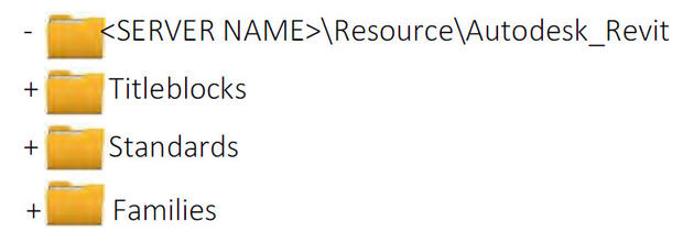
9.7.2 Project Folder Structure
The following folder structure is provided as an example arrangement, designed to encourage compliancy with the strategies contained within this standard.
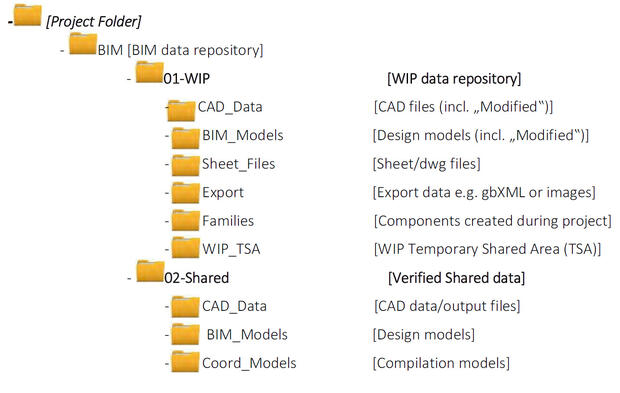
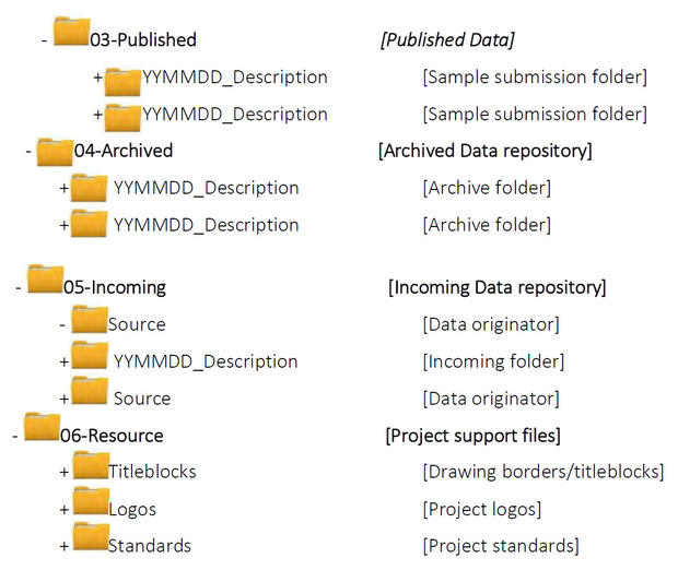
No spaces are to be used in the folder naming as this can potentially interfere with certain file management tools and collaboration across the internet.
9.7.3 Component Library Sub-Folders
All locations for the storage of Family components shall be sub-divided as follows:
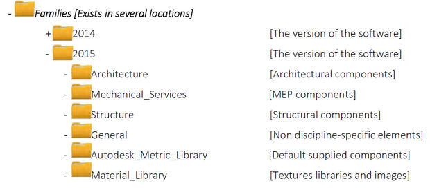
The individual disciplines shall then be broken down as follows, with new sub-folders added as required by additional functionality in the software.
Architecture Components
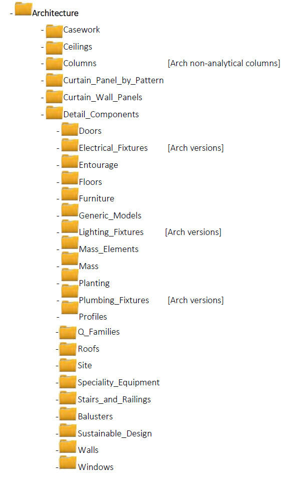
MEP Components
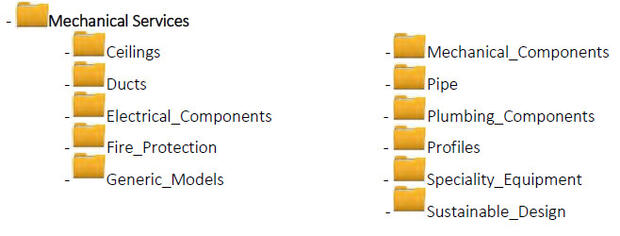
Structural Components
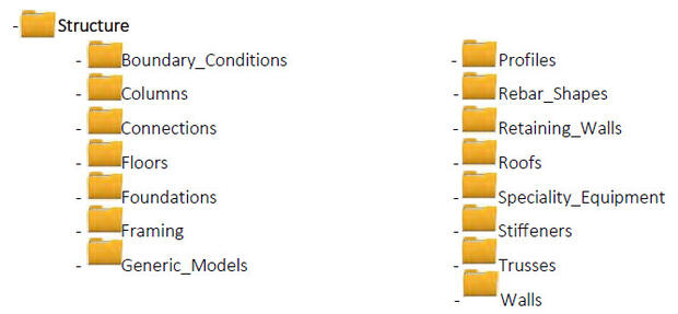
Non Discipline-Specific Components
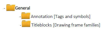
12 NCS, v5 - Distinguishing features are distinct, different, or defining characteristics that specifically describe special information related to the
items contained in the schedule. Depending on the schedule's complexity, each schedule may contain multiple columns for features.
Glossary
Appendix A - BIM Uses
This Appendix is a companion to the DCAMM BIM Guidelines document created for the use of DCAMM service providers on projects. These BIM Uses will be updated to remain current with industry BIM development and technology changes.
Primary Authorship:
AEC Infosystems, Inc. under contract to DCAMM for the authorship of the DCAMM BIM Guide and this Appendix.
Using the BIM Execution Plan Template (BIMXP)
As soon as possible following a contract award, the prime BIM Manager will schedule a Conditions of Satisfaction (CoS) meeting. At this meeting, Lean Value Mapping is strongly recommended to identify the project Conditions of Satisfaction (CoS), and the BIM Uses relevant to the project. Prior to the CoS meeting, the BIM Manager will become familiar with the BIM Execution Plan Template (BIMxP), and Appendix A – BIM Uses document in the BIM Guide. The BIM Uses define DCAMM’s understanding and expectations for how BIM may be used on DCAMM projects.
The BIMxP template has several pre‐defined project Conditions of Satisfaction categories. Each category has supportive BIM Uses to be identified for project execution. The team sets a priority (1‐High, 2‐Medium, and 3‐Low) using the “CoS No.” pull‐down menu, and selects the responsible parties by using the pull down menu.
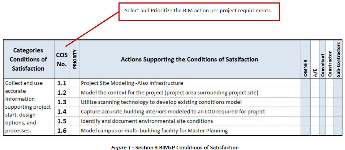
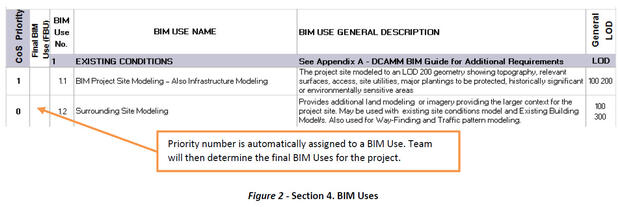
Section 4. The BIMxP template will automatically assign the priority number from the CoS action on sheet 3 to a corresponding BIM Use (Section 4) In Section 4, the team will then finalize the BIM Uses for the project.
1 Existing Conditions Modeling
1.1 BIM Project Site Modeling – Also Infrastructure Modeling
Descriptions: An existing ground surface model of the project site and any occupying or relevant structures and utilities affecting the project. The LOD for these contextual site elements may be lower than a building or partial building of the project. Paving, grades, sidewalks, curbs, operational elements that cannot be disturbed and other elements supporting the project requirements as needed for the project should be shown.
A separate discipline model that includes new topography, site work, landscape, retaining walls and surrounding area contributing to drainage, environmental requirements and roadways supporting project requirements. Geo-referenced per the BIM Manager’s specifications.
Responsibility: The Project Design Team has this responsibility. DCAMM will provide any existing CAD or GIS drawings. Additional Information includes Google Earth, photos, and scans.
The design team is responsible for a site model supporting the project requirements. The team will define the LOD for the site model through the project phases in the BIMxP.
At a conceptual level, a combination of CAD with 3D overlay, Google Earth with 3D overlay, photographs, and Sketch-up (to be converted to Revit) may be used with the building shell for visualization, setbacks, site analysis, and review.
Model Elements:
LOD 200 - Generic site element modeling will include:
- Approximate size/shape of foundation element
- Approximate size/location of utilities and structures
- Approximate code and clearance requirements
- Approximate pipe material
- Rough modeling of site grading
- Local structural building grids defined in model and coordinated with global state plane coordinate system for site model (set by the BIM Manager for the entire project).
LOD 300 - Accurate for cut, fill, and volume estimations.
Changes in utilities at site are to be modeled at LOD 300. Document the utilities to be modeled in the BIMxP.
Utilities include:
Utilities should be modeled to face of structure and connection
- Pipe drainage system (including storm water removal)
- Sewage systems
- Electrical lines
- Communication lines (copper, fiber, co-axial)
- Gas lines and fuel lines
- In-ground heating or cooling lines
- Pneumatic lines
- Water
- Steam
Color Code Requirements
The American Public Works Association (APWA) Uniform Color Codes shall be used for modeling elements
- Red - electric power lines, cables, conduit, and lighting cables
- Orange - telecommunication, alarm or signal lines, cables, or conduit
- Yellow - natural gas, oil, steam, petroleum, or other gaseous or flammable material
- Green - sewers and drain lines drinking water
- Blue - drinking water
- Purple - reclaimed water, irrigation, and slurry lines
- Pink - temporary survey markings, unknown/unidentified facilities
- White - proposed excavation limits or route
Data Requirements: Data standards and formats such as OmniClass and COBie, and those from MassGIS, BOMA, NIST, OSCRE, IFMA, MSCBA, American Chemical Society, NFPA, and other applicable specialized standards such as CPTED-RED1, shall be used in the appropriate domains per consultation with DCAMM.
Deliverables: Civil 3D, Revit. Navisworks Design model may be linked to site model for other BIM Uses.
Software: Sketch-Up, Revit, Revit MEP, Autodesk Civil 3D, Navisworks, BIM 360 (in review). ”Software” includes add-ins and add-ons that supplement or augment the mentioned packages.
1.2 Surrounding Site Modeling
Description: Surrounding site modeling includes the area, buildings to a defined LOD, and infrastructure (roads, bridges, railroad, subways, streetcar lines) adjacent to the project site necessary for project analysis, review, or decision support. Examples: Line-of-sight, Sun Shadow Analysis (heliodon), and Future Master Planning. New and or temporary traffic patterns, access, and construction logistics may require surrounding site modeling.
A local structural building grid may be defined in the model and coordinated with global state plane coordinate system for the site model. (Set by the BIM Manager for the entire project – See Survey Control Points in BIM Guide)
Responsibility: The design team, civil engineer, and DCAMM BIM Manager provide existing information. The design team is responsible for a site model supporting the project requirements. The team will define the LOD for the site model through the project phases in the BIMxP. The Design model is linked to site model for other BIM Uses.
Model Elements: LOD 100 - 200: CAD with 3D overlay, Google Earth with 3D overlay, photographs and Sketch-Up (to be converted to Revit) may be used with building shell for visualization, setbacks, and site analysis and review. New roadways and bridges are to be modeled for BIM based reviews. The team shall document the software used for modeling and any additional tools for BIM based construction documentation.
Data Requirements: OmniClass and data standards DCAMM may reference such as those from MassGIS, BOMA, FICM, OSCRE, MSCBA, NFPA, GIS conventions such as WCS84, and other applicable specialized standards such as CPTED-RED, shall be used in the appropriate domains per consultation with DCAMM.
Deliverables: BIMs integrated with project site model. Site model may
Software: Sketch-Up, Revit, Revit MEP, Autodesk Civil 3D, Navisworks, BIM 360 (in review)
1.3 Existing Conditions – Laser Scanning
Description: 3D laser scanning (based upon approved survey control points) produces dimensionally accurate and detailed 3D point clouds (PC) of existing facilities and assets. The point cloud is typically a large file or series of files, unwieldy, and lacking in intelligence relative to the BIM, which may be developed from it. In some cases, the point cloud will need to be further transformed into a BIM, while in other cases the point cloud will only partially be transformed as required to interface with new construction for the project at hand. In either case, the scanning team may employ some post-processing procedures and techniques to substitute portions of the PC with vectorial objects later usable by BIM systems. Some piping, valves, and racks and other equipment are typical examples.
The scope of this Use Case is to produce a PC of existing conditions, which can be used as a reference against which a BIM, created by others, will be referenced. The BIMxP will specify which team participants will do the transformation to BIM, (sometimes depending on the software used by the scanning team), and which participants “add intelligence” as the point cloud is transformed to BIM. The various BIM managers will be responsible for coordination as the PC is moved among teams.
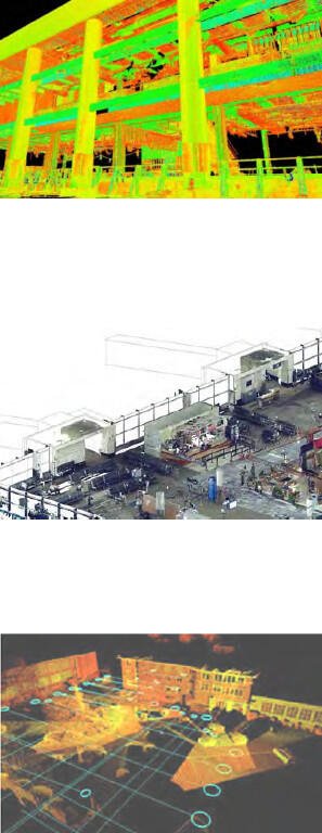
The scanning team will create a PC suitable for export to designated BIM software, or suitable for import to the BIM software as agreed in the BIMxP or other contractual documents.
The PC data can be integrated into BIM authoring software for model development and Navisworks for review. Survey reference points allow the model and the scan to be aligned accurately to the State coordinate system or other agreed reference plane for DCAMM’s use.
Point Cloud Development: In this Use Case, the laser scan PC output may contain some vectorial graphics, again according to the laser scanning software used in the scan and in its post-processing. The PC will be developed to include scans of the building features required by the BIMxP and/or by contractual agreement. Typically, laser scans of opened walls and otherwise normally inaccessible spaces, infrastructure, and equipment of historical buildings, are good candidates for laser scanning. Laser scanning fees are typically less than fees for opening, closing or restoring portions of historically valuable buildings. The features that are scanned will be determined by DCAMM’s needs.
Responsibility: Laser scanning may be a sub-contracted part of the architect’s, constructors, or CM’s scope of work, or to a third party. The responsibility for transformation of point cloud to BIM will be codified as a contractual matter. It will frequently the A/E participants who “consume” the point cloud, add intelligence required for design development, and produce the BIM documentation.
- Coordination for Survey Control Points: Coordination and communication between DCAMM PM, the scanning party, the BIM Manager, and other responsible parties to share “survey control points” for laser scanning activities, scan creation, and model development.
- BIM Development from the Point Cloud: BIM production will follow DCAMM BIM Guide standards, and the LOD and model elements defined in the project BIM execution plan. Not all scanned elements will be modeled.
Deliverables: Deliverables will include the 3D point cloud, BIM(s) as specified in the BIMxP, and Navisworks and .rvt files.
Software: Identify point cloud development software (editing and viewers) and deliverable specifications to DCAMM. Result must be suitable for use in Revit Architecture, MEP, as required for scanning and modeling scope. Identify software in the BIMxP.
References: See: MassGIS Data Layers List, MassGIS Standards
1.4 Existing Conditions – Interiors Modeling
Description: This is a spatially accurate model of existing spaces, building system components, and equipment. Data necessary for design option decisions may be required as part of BIM development. The model can be used to explore design options, design coordination, analysis, and facilitate client decisions. The Laser Scanning general description in Section 1.3 (above) will apply to this building interior focus.
Model Development: The model can be developed from existing documents, site measurements, and/or laser scanning. Assets and spaces are typically LOD 300. Modeling follows DCAMM BIM Guide and BIMxP development. The Model Development context for Existing Conditions in Section 1.3 applies to this building interior focus.
Responsibility: Modeling and optional laser scanning may be part of the architect, constructor, or CM’s scopes of work, or sub-contracted to a third party. DCAMM retains approval authority. (See Laser Scanning BIM Use for laser scanning requirements).
Deliverable: Deliverables include native file (.rvt), data/QTO reports, COBie format or spreadsheet as approved by DCAMM, and source point cloud as backup for model validity.
Software: Revit suite (Architecture, MEP, and Structure) per building elements and systems modeled. Use suitable point cloud viewer and editor.
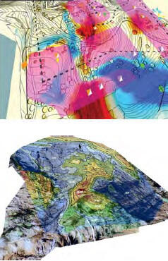
1.5 Geo-technical Modeling
Description: This covers a visual, dimensionally accurate model of the geo-technical analysis report supporting project scope and requirements. Modeled, located, and identified elements may include soil borings, protected lands (wet lands, marshes, animal habitats, topographical barriers, brown fields), environmental and superfund site issues which bear on the progress of the project.
Responsibility: Responsibility typically falls to the civil engineer, as identified and documented in the BIMxP. Geo-technical information is the responsibility of the engineer, as identified and documented in the BIMxP. Modeling may be created by a third party or other member of the engineering team.
Data Requirements: Geo-technical data will be defined and documented in the BIMxP.
Model Elements: Site and land elements are to be defined to support the project requirements.
Software: Software includes Civil 3D, Revit Architectural, Navisworks, and other software used documented in the BIMxP.
1.6 Site Modeling – Horizontal Construction
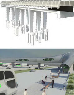
Description: Roadways, raised bridges and walkways, and transportation structures such as pedestrian tunnels are all examples of horizontal modeling needs on DCAMM projects. Combined with Civil 3D roadways sites, the project team can effectively model the total environment of DCAMM facilities. As with vertical construction, horizontal structural modeling is done with product and building element objects. These objects can be analyzed with ROBOT. Included in this category are power line utility feeds, and pipelines, whether above ground or in ground.
A separate discipline model may include new topography, site work, landscape, retaining walls and the surrounding area contributing to drainage, environmental requirements, and paths and roadways supporting project requirements. These models will be Geo-referenced per the BIM Manager’s specifications.
Responsibility: The project design team and DCAMM provide any existing CAD or GIS drawings. Additional Information includes Google Earth, photos, and scans. The design team is responsible for a site model supporting the project horizontal construction requirements. The team will define the LOD for the site model through the project phases in the BIMxP. At a conceptual level, a combination of CAD with 3D overlay, Google Earth with 3D overlay, photographs and Sketch-up (to be converted to Revit) may be used with the building shell for visualization, setbacks, site analysis and review.
Data Requirements: OmniClass is used for most project types. The OmniClass fields for families in Revit will be used. Local structural building grids shall be defined in the model and coordinated with the global state plane coordinate system (selected by the BIM Manager for the entire project).
Model Elements
General description and LOD 200 - 350
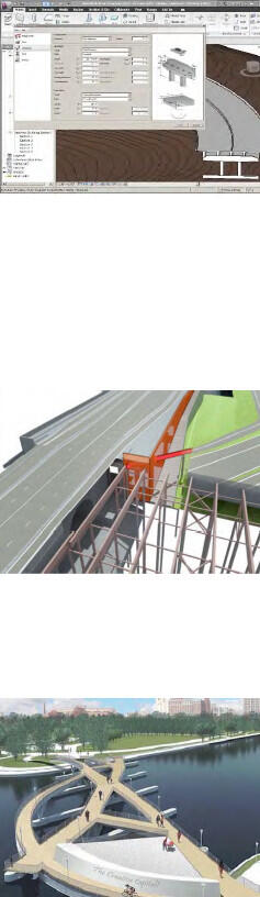
- Bridge or structure building elements
- Columns
- Foundations
- Communications
- Other discipline building elements
Horizontal Structures:
LOD 300 – 350
- Foundations or Pilings
- Columns, walls, parapets
- Girders, superstructure, deck
Deliverables: 3D Site Model in Civil 3D. Utilities in Civil 3D and Structures in Revit. Revit Design model in Navisworks may be linked to site model for other BIM Uses.
Software: Software mentioned herein such as Revit, Revit MEP, Revit Structure, Autodesk Civil 3D, Navisworks, includes add-ins, add-ons, and plug-ins that were actually used to supplement or augment the mentioned packages to create the BIM deliverable. Additional software packages compatible with 3D DWG may be submitted for DCAMM approval.
2 Design and Building System Authoring
Each discipline team shall model its contribution to the design options and final design.
These individual models are Work in Progress (WIP) models. These are reviewed, and then federated with other models for ongoing clash coordination (weekly or on a pre-determined schedule). Upon completion, all models are federated into the architectural model to create the Design Intent model of the final design solution.
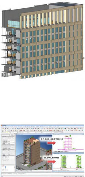
2.1 Architectural Model – LOD 200 – 300
Description: This model is used to explore design options, and serves as a base model for the federated design intent model, design analysis, and other BIM Uses. It contains the BIM elements assigned to the architectural authoring team. The elements, LOD, and model progression should be defined in the BIMxP. This base model is used for discipline integration, and must support “clash
avoidance” and model checking.
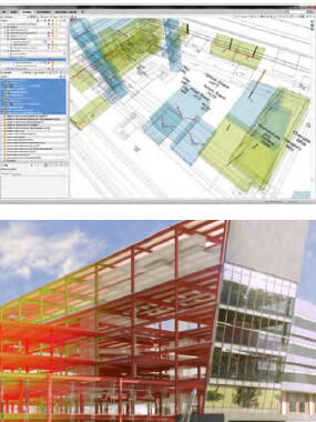
Responsibility: Architectural design team has responsibility for this. The BIM Manager will use it as a basis of model integration with other disciplines. Defined coordinates for all disciplines are in this model as specified in BIMxP.
LOD: Progressive from LOD 200 (spaces) to Construction Documentation for contractor handover.
BIM Architectural Elements: Design Development
- OmniClass Spaces by Function (Table 13) are used in conjunction with DCAMM Room Numbering, functional designations, secure spaces designations
- Partitions and Walls – Dimensionally accurate interior partitions and exterior walls. This LOD includes assemblies supporting other BIM Uses, budgetary estimates, estimates, visualization, space validation conformance, and other discipline models. DCAMM wall naming conventions must be followed. This LOD includes doors, windows, and openings. Finishes are to be included within wall types.
- Interior, Exterior Soffits, overhangs, sun control elements, parapets, screening elements
- Architectural precast
- Floor, Ceiling, and Roof systems, dimensionally accurate (slopes as needed) with floor to floor dimensions, and used as a basis for coordination with Structural and other discipline models. Assembly data supporting construction documentation, 3D detailing, QTO and estimating, and analysis.
- Soffits and openings shall be modeled along with louvers, diffusers, and other building elements required for visualization, QTO, Schedules.
- Vertical shafts, elevators, stairs, ramps (railing systems) and other horizontal and vertical conveyence systems
- Model mechanical, electric, and plumbing fixtures and equipment requiring architectural space.
- Examples: LOD - 300 Toilets and stalls, sinks
- Consideration must be given to Mechanical Equipment Clearance Zones for access, service space requirements, meter reading, clear space required by relevant code authorities, and operational elements needing service space. Zones may be modeled as transparent or translucent solids, named, and classified and on separate model layers.
- Interiors including casework, shelving, interior built-in elements, furnishings (fixed and loose furniture and furniture systems,), furniture, fixtures, and equipment (FFE) if not supplied by others, must be included in the architectural model.
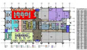
Specialty Equipment, including food service and medical equipment if not supplied by others, will be included in the architectural model.
Deliverables: Revit Model, federated model for handover, used as basis for Record (As-Built) model.
Software: Sketch-Up during options and programming (converted to Revit) Revit Architecture for architecture model.
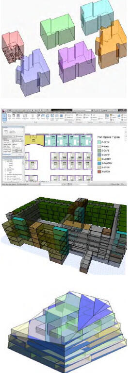
2.2 Space, Accessibility, and Circulation Requirements Modeling
Description: DCAMM requires the design team to model space, circulation areas, and accessibility using national accessibility standards, consistent modeling methods, and DCAMM space and data standards. When modeled correctly, spaces can be validated against the project program, functional space needs, and circulation rules using a model-checking tool.
Definition of BIM Space Modeling and Circulation
- Spaces are bounded areas or volumes created using the BIM authoring application’s space definition tool with a room (space) tag to contain its designation and the required space classification information.
- Spaces are automatically generated to the face of the wall in areas enclosed by walls such as rooms, or may be modeled as stipulated spaces that are operational or organizational in nature rather than being defined by physical wall elements. Examples: a reception space, a department, a mezzanine, an elevator lobby space. To the maximum extent possible the BIM authoring tool should be used to automatically detect boundaries and calculate areas and volumes of the resulting space elements. Extensive manual delineation of areas in a large project is error prone, relatively inflexible as space sizes evolve, and costly.
- Circulation defines the accessibility allowed for various spaces within DCAMM buildings. These conditions also determine the ease of entry and egress to and from different spaces in the building in case of emergency; for secure transfer and transit, as well as access to specific spaces in a building for special populations such as travelers, security personnel and prisoners, and access for people with disabilities.
- Public circulation is understood as all those areas for the use of general public inside the building
- Restricted circulation has a controlled interior entry; the use of these zones is limited to screened visitors, and other designations in the project program.
- Secure circulation includes all areas intended for the circulation of employees only. It is under the control of the relevant law enforcement and/or security authorities such as the Massachusetts State Police, college and university police forces, Department of Correction/County Sheriff staff, transit police, and the like.
- Spaces are color coded and a legend or schedule of spaces created.
Model Elements:
- All spaces/areas greater than 9 square feet (> 9 SF) in plan area, relevant to the project, existing, changed, or new, shall be modeled.
- The BIMxP will specify the exact figure below which a space need not be modeled, and therefore will not be tracked by DCAMM. For post-911 security reasons, DCAMM may set a lower figure for accessible space.
- For post-911 security reasons, accessible above-ceiling spaces should be modeled and tracked.
- The BIMxP will specify the exact figure below which a space need not be modeled, and therefore will not be tracked by DCAMM. For post-911 security reasons, DCAMM may set a lower figure for accessible space.
Additional BIM elements and data shall include:
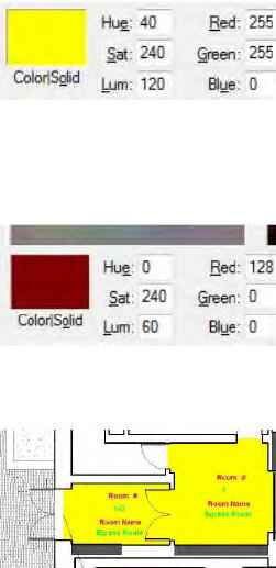
- Space Name and Space ID Number per DCAMM requirements
- OmniClass Table 13 - Spaces by Function
- Space security classification – Minimum secure and non-secure space identification
- Elevator, containing space name, space ID number, security level
- Stair, containing space name, space ID number, security level
- Ramps, ramp slope, ramp designation
- Wall LOD 200, for space boundary, no specific wall attributes required for space validation
- Space Door(s), LOD 200, door number assigned to space on ”secure” side or door number or name derived from space on secure side of door; no specific door attributes required
- Color Code: DCAMM may use a color coding system for certain space types, such as Yellow: public, Red: Non-Public, Green: circulation, and so on.
- Colors may be modified (lighter, or less intense as needed) to produce suitable displays and printed documentation that may be required from time to time.
Space Calculations:
Area measurements will generally be determined by the standard appropriate to the building/facility, such as BOMA for office type structures and FICM for higher education facilities. Variations from any of these standards may occur due to particular charge back arrangement between the occupant(s) of the facility and the “owner” of the facility, DCAMM.
- Gross Area: the footprint of the building or floor to the outside face of wall
- Usable Area: the spaces to the face of wall (Example: room). It does not count the space under columns in the room.
- Program requirements describes square footage based on Usable Area, which is the actual occupiable area of a floor or building used solely by the client. This figure represents an accurate reflection of the project space needs so the size of the proposed space should vary as little as possible from the Usable Area listed in the RFP.
- Usable Area is determined by measuring the entire floor area of the premises (or such other space) bounded by a line established by the predominant inside finish of the permanent outside building walls which abuts the floor (not from the inside face of windows) and by the interior surface of corridor walls or other demising walls.
- No deductions shall be made for columns or other projections necessary to the building structure or systems or for partitions subdividing the premises. Under no circumstances shall the Usable Area include elevator shafts, vestibules, stair enclosures, elevator machine rooms or other building equipment areas, janitorial, electrical or mechanical closets, loading platforms, or restrooms (unless they are included in the Agency Specifications and in addition to the restrooms required to meet code), irrespective of whether the Agency occupies the entire floor or the entire building.
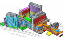
- Rentable: Formula supplied to Tenant space.
Codes: Americans with Disabilities Act (ADA) and the Architectural Barriers Act (ABA) are two applicable sets of requirements that also will have reporting and legal implications.
Deliverables: Additional model tools may be used during early design. See the list of space planning tools in the DCAMM BIM Guide. Space views and space reports are required for design meetings and communication during design development. The Final design model shall be in Revit.
For Model Validation: A single file containing the BIM exported to IFC 2x3 format or most current approved IFC version. See BIMxP for the project has approved software versions.
2.3 Structural Model
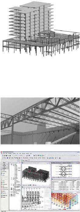
Description: The structural model is a discipline model of the structural system of an existing or proposed design. The system, detailing responsibilities, and modeling LOD shall be documented in the BIMxP.
Responsibility: The Designer of Record, the Architect unless otherwise specified, is responsible for all activities associated with the project, including the activities and products of its sub-consultants. Under the aegis of the Designer of Record, the Structural Engineer is responsible for structural systems in the model. The design team may begin design in the architectural model and share modeling during design options. The modeling responsibility shall be documented in the BIMxP.
Modeling Includes the (proposed and/or existing) specified structural system, ready for handover and construction detailing
- Foundations – Any foundation type, Structural Foundation Walls
- Framing, steel columns (correct shape & size), steel joists (C-joists, open web, joist girders, steel beams (correct section shape and size)
- Precast Concrete elements – Hollow Core Plank at LOD 100 - 200 may be modeled as slab; at LOD 300 - 350 if coordination with mechanical is required.
- Cast-in-Place Elements
- Floors, including openings
- Wood posts, columns
- All other joists and wood trusses
- Solid wood and Laminated Beams
- Fireproofing, if required, using a 2” clearance for clash avoidance, detection.
- Load Bearing Walls and openings – masonry, concrete, cold-formed steel and wood (model overall wall thickness)
- Design Team Optional Modeling may include steel reinforcement, embeds in concrete, additional steel elements (including post-tensioned cables), angles for openings, channels for mechanical units, metal decks, elements required for coordination, QTO, and clash avoidance or clash detection.
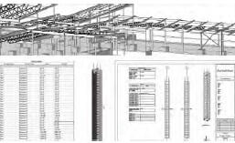
Data Requirements: OmniClass, UniFormat, and COBie data
Deliverables: Structural discipline model, shop drawings model integrated into structural model, record (As-Built) model
Software: Revit Architectural, Revit Structural, Tekla. Other software documented in the BIMxP
2.4 HVAC Mechanical Systems
Description: This is a separate discipline model, which is modeling of a system for decision support and analysis, made ready for detailing and fabrication.
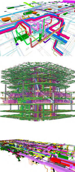
Responsibility: Under the direction of the Designer of Record, multiple team members assume this responsibility. How the system is modeled across phases, and handover for detailing and pre-fabrication, is to be diagrammed and defined in the BIMxP.
The various HVAC and fuel systems modeling shall follow the LOD designation provided in the AGC LOD Manual.
Model Elements:
- Model elements are typically ”smart objects” for equipment that includes, fans, VAV boxes, and controls, compressors, chillers, cooling towers, air handlers; other equipment required for construction documentation, and QTO; and handover for pre-fabrication.
- LOD 200 – Generic elements, approximate size, shape, location. Shaft requirements in model. Maintenance space requirements
- LOD 300 – Detailed elements, Contractor-submitted actual elements including dimensionally accurate elements, air supply location, connections, piping, valves, insulation.
- Actual wall and floor penetrations.
- Allowance for hangers, supports, vibration
- LOD 400 – LOD 400 is characterized by manufacturer and contractor modeling elements for field installation; finalized data requirements in Commissioning; As-Built (Record) Model.
Data – Data include performance and manufacturer required data for analysis, Record Model and FM, OmniClass and DCAMM facility handover.
Deliverables: Deliverables include structural discipline model, clash avoidance among Architectural, Structural, and HVAC; equipment lists and COBie data
Software: Revit MEP, other software documented in the BIMxP, Navisworks, Solibri Model Checker.
2.5 Plumbing and Fire Protection
Description: Separate discipline models - Minimal modeling of system sufficient for shop modeling and fabrication.
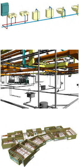
Responsibility: Architect, Mechanical Engineer responsibility defined by phases in BIMxP
Modeling Requirements:
The plumbing and fire protection systems modeling shall follow the LOD designation provided in the AGC LOD Manual.
- Waste and Vent: piping at or over ¾” inside diameter (i.d.). Model insulation unless noted and approved in the BIMxP.
- Supply: piping at or over ¾” i.d. Model insulation unless noted and approved in the BIMxP. Domestic Booster Pumps
- Fixtures: sinks, toilet fixtures, urinals, water tanks, floor sinks, and other fixtures. LOD 200 – 500 for As-Built (Record) Model. Include performance data for analysis.
- Fire Protection: Sprinkler lines, sprinkler heads, fire protection pumps, stand pipes, wall hydrants, fire department connections, risers and valve clearances. Sprinkler heads with virtual label, performance, and installation date.
Data Requirements: COBie data and schedules for construction documentation and commissioning data per project requirements.
Deliverables: Discipline model, COBie data and commissioning information, construction drawings to A/E
Software: Revit Architecture, Revit MEP, other applications with add-ons and plug-ins as documented in the BIMxP
2.6 Electrical Alarm Systems
Description: As separate discipline models or part of the electrical model, the primary components of the electrical, lighting, alarm systems and building automation systems (BAS) controls.
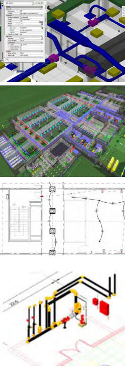
Responsibility: Electrical Engineer, Architect, Interior Designer. Modeling responsibility by phases will be documented in the BIMxP.
Information Requirements:
- List of major equipment consuming electricity:
- Chillers, Boilers, Compressors, Condensers, Unitary Equipment, Air Handlers, Transport Elements (e.g., people movers):
- Electrical phases, Load, Voltage, System Type
- List of equipment (if any) for generating electricity:
- Generators, solar panels, wind turbines, output voltage, system type, generating capacity
- List of equipment for storing electricity:
- Uninterruptible power supplies (UPS), connected load, uptime
- Emergency lighting battery units, exit signage
- General-purpose electric demand in/for building
- Space: power density for lighting, appliances, equipment, outlet requirements
Modeling Elements:
- Data, power, and telecommunications: Elements include interior and exterior transformers, emergency generators, main and distribution panels, and switchgear including access clearances. Main Intermediate Distribution Frames (IDF), outlets, switches, junction boxes. Include BAS devices and controls, and electric building products for QTO.
- LOD 200 with generic lighting and performance data for analysis.
- LOD 300 actual fixtures with correct performance and load data and location.
Data Requirements include COBie and commissioning data, classified according to OmniClass and UniFormat, cut-off switch locations, and reset
Deliverables include discipline models, distribution panel schedules and other equipment schedules, sensor locations, COBie data, commissioning data in model, and QTO for cost estimating.
2.7 Interiors
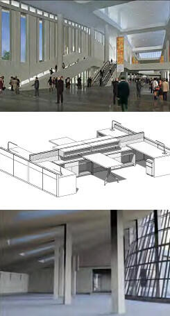
Description: Modeling of interior design options, materials and finishes, details, casework, furniture, fixtures and equipment (FFE), furniture systems, signage, and way-finding, support for lighting power locations, LEED and daylighting.
Responsibility: Responsible team members include the Architect, Interior Designer, Lighting Consultant, Furniture Contractor, all of whom coordinate with the electrical engineer for lighting outlet placement, telecommunications equipment and fixtures and surveyors. Tenant representatives may be involved per scope of work.
Model Elements: Elements will include interior partitions, soffits, ceiling grids, moldings, base, architectural details, lighting, FFE, ramps, raised floors signage. Materials and finish schedules. Elements modeled to support QTO and estimates, LEED, lifecycle costing.
Survey Points: Survey control points identified during pre-construction should be esthetically integrated into the final floor design finishes as brass, steel or other permanent material markers for future facilities work.
FFE: BIM will be used for QTO, estimating, procurement and pre-fabrication.
Deliverables include renderings and model views as requested for design review. Model elements are to be integrated with the Architectural model for construction documentation, FFE schedules, and material and finishes schedules.
Software: Revit Architectural, Navisworks, rendering visualization software identified in BIMxP.
2.8 Tenant Build-Out
Description: Tenant projects are all sizes, including simple kiosks, office spaces, technical laboratory spaces, and other specialized-function spaces. The tenant will work with DCAMM to determine the space, scope, and requirements for tenant documentation, including BIM.
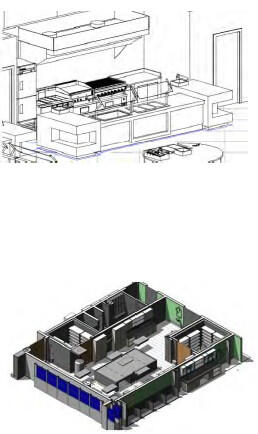
Responsibility: The tenant’s designer is required to inform DCAMM concerning tenant BIM and CAD standards that may conflict with DCAMM standards. The tenant will provide models and data per DCAMM-provided requirements.
DCAMM will supply any existing information available for the space and applicable code requirements
Modeling Elements: All disciplines
- All new building elements in the space, equipment, MEP, and specialty items will be modeled at LOD 300 for review by DCAMM Tenant Coordinator.
- Food Service will conform to all applicable codes. Clash Detection and resolution will be performed on the design prior to construction documentation completion.
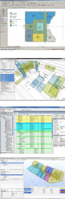
3 Analysis and Reporting
A major benefit of BIM is the ability to analyze the model for performance, design conformance, and to run reports of critical design information as the model changes.
3.1 Area and Space Program Validation (SPV)
Description: The BIM file, specifically spaces and bounding elements, including floors and stories, is analyzed using model checking software. Attention is given to the file format required by the checking software, and its applied rules. A report of deviations to be reviewed and addressed by the design team is generated.
Responsibilities: Design Team, DCAMM Review
Spatial Program Validation (SPV) is done by the design team, reviewed and approved by the DCAMM team. SPV assesses the degree to which the modeled design meets all of the DCAMM defined space requirements. Such assessments are ongoing during design develop-ment, and used in design review meetings.
SPV during concept design focuses on the following things:
- A pre-check of the model for valid model structure and for completeness, relative to what is required for space in the DCAMM BIM Guide and the project program
- Measurement of space areas, by space type and occupant, or by space type and function, and required attributes
- Assessing and documenting differences between space areas provided in the design and what is required in the space program for the project, organized by space type and occupant or space type and function
- Assessing and documenting differences between the design and requirements in other areas (e.g. space proximity, adjacencies, floor location, etc.)
- The DCAMM review is a crosscheck of the design option conformance. Design issues will be communicated back to the project design team for resolution before the design is accepted by DCAMM.
Space/Area Modeling:
- Assignable Areas and Non-Assignable areas modeled to face of wall and designated boundaries
- Gross area measured to the outside face of wall
- Space modeled as volumes, calculated as area in square feet and cubic feet
- Model plenum spaces, interstitial spaces as specified separate volumes
Minimum Space Attributes:
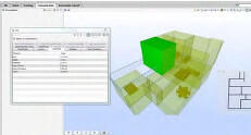
- OmniClass Table 13 – Spaces by Function
- Existing numbering structure in existing construction or renovation
- Categorize as public, private, secure space designation
- Generic assignment of MEP elements per square feet. Example: Number of light fixtures per area
Software: Authoring tools include Revit Architecture, Trelligence Affinity, and Solibri Model Checker
3.2 Design Options
Description: The design team will develop design options in BIM supporting the project program requirements. The options will be modeled to support model analysis and BIM based reviews. Set-based design may be used for this process.
Responsibility: The design team will work with other disciplines to determine modeling level of effort for the design options. Example: If energy modeling is required for design options then the team will provide a model that supports data for energy analysis. The BIMxP will document design option uses.
Model Requirements:
- LOD 100 – Generic massings, approximate size, shape, location
- LOD 200 – Modeled with floors, generic building envelop for analysis and calculations
- LOD 300 – Generic but identifiable building elements, envelope, spaces, zoning for preliminary HVAC. Model integrated with site model for siting, sun-shadow (heliodon) analysis, square foot calculations for costing
Deliverables: Structural discipline model, Clash avoidance between Architectural, Structural, and HVAC, Equipment lists, COBie data
Software: Revit MEP, Navisworks, Solibri, and other software, add-ons, and plug-ins as documented in the BIMxP
3.3 Model Checking – Program Compliance
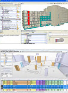
Description: Model Checking is a rules-based activity that automates model review for design program, modeling quality, data, and some code conformance. DCAMM’s ability to treat existing rules as templates and modify them, and to write completely new rules, expands model checking usefulness to include program checking as well as model technical soundness.
Examples: Accessibility code conformance, egress path length, corridor width. QA/QC – Check for model quality. Examples: check door sizes, swing direction, door width; check that walls meet floors and ceilings; check that walls heal at corners; check that space entities defined in the BIM are properly bounded (i.e., do not “leak”)
Responsibility: BIM Manager with design team input have this responsibility following a process similar to clash avoidance. Select and configure rules to be run against the model.
Modeling: Integrated discipline models required to review for code compliance or design requirements.
Recommendation: Use model checking to determine that required data has been added to model elements. Example: Check that assignable spaces have a space number and/or name.
Software: Solibri Model Checker
3.4 Clash Avoidance and Detection
Description: Note: The graphics in this section are available full size for download with the Clash Matrix Graph (2).wmv. The project PM will provide the materials or location on the DCAMM website.
Clash Avoidance is a primary method to minimize interferences between building elements using “clash detection” software. Starting in design and continuing into construction, teams will regularly federate current models to identify any conflicts in geometry and provide a design resolution.
Responsibility: The Design Team BIM Manager will integrate the discipline models and check for interferences during design and prior to each construction documentation issuance. This BIM Manager will be responsible for using clash detection software, creating and performing visual walk-throughs of the model, creating section and perspective captures, support review, and conflict resolution. The BIM Manager will update the DCAMM Clash Detection Template and submit it to the project manager for review.
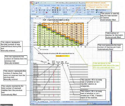
Deliverable: These conflicts will be cooperatively resolved in review meetings. What the conflicts are and how they are resolved is reported to DCAMM and the team using the DCAMM Clash Matrix Report template.
Software: Navisworks and Solibri Model Checker
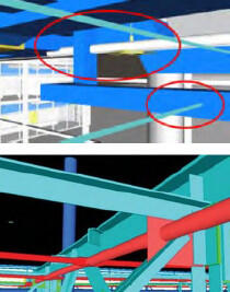
The DCAMM Template
Clash Matrix Graph(2).wmv
The clash matrix template is an excel spreadsheet designed to standardize clash reporting to DCAMM.
The Clash Matrix has identified batches, colors, and reporting requirements.
The batches will be documented in the Clash Report Template.
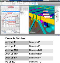
Clash saved views will be provided in the following folder structure to DCAMM:
- Date
- Discipline
- Floor
- Elements
- Floor
- Discipline
3.5 Structural Analysis
Description: Model based analysis of structural design to determine fitness for use. Required structural analysis is to be documented in the BIMxP. BIMxP will document the software use and the projected outcome for the activity.
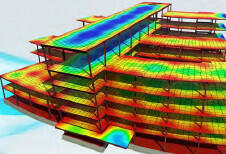
Responsibility: Structural Engineer, Structural model coordinator, Design team BIM Manager.
Deliverable: Structural analysis report and graphics for design reviews.
Software: Revit Structural, Web Add-in, plug-ins and other analysis software to be documented in the BIMxP.
3.6 Equipment and Maintenance Clear Space
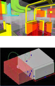
Description: Required for MEPF, this modeling covers major equipment and elements requiring defined access or maintenance space. Consideration should be given to typical maintenance cycles and continuity of operations so that adjacent equipment can be serviced at the same time when necessary. Consideration must be given to replacement movement paths and accessibility of large equipment. (The supporting structure along intended movement paths should be coordinated with structural considerations.)
Provide a level of detail for equipment showing not only how it will fit in spaces provided (shown in the design intent BIMs), but also how equipment can be maneuvered into the designated spaces during building construction and removed for maintenance or replacement after construction.
Responsibility: BIM discipline coordinators are responsible for elements in their models. The BIM Manager will do review as part of clash avoidance. The visualizations and views of the model showing the maintenance space will be reviewed by the facilities team.
Note: These views may be saved to support the BIM use case Model for Maintenance Training.
Modeled Elements: Model the access space as a transparent or translucent shape. Example: red cube in illustration. The color and applicable naming convention of the clearance space is to be documented in the BIMxP. The volume is not counted as a building element in QTO.
Deliverable: BIM based review with DCAMM Facility Management team for approval.
Software: Revit Suite, Navisworks.
3.7 Budgetary Costing (LOD 200 – 300)
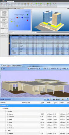
Description: Budgetary Cost uses BIM spaces, major building elements with historic square foot costing data, project type, region, and construction type, to calculate budgetary estimates. Used as a decision basis in design options review and selection. Define milestones and LOD in BIMxP.
Responsibility: AE team, CM during pre-construction services with FM input.
Model Elements: Floors, walls, spaces, structure, roof, curtain wall and/or windows (building envelop), with specifications for parametric costing of partitions, lighting, ceiling grids, etc.
Data: Classify according to OmniClass and UniFormat systems. Define or identify historic cost data in BIMxP.
Deliverables: Periodic costing reports for design options.
Software: Revit Architecture, Microsoft Excel, VICO Office, online costing data, and other software documented in BIMxP.
3.8 Quantity Take-Off (LOD 200 - 350)
Description: As the model develops, a progressively more complete and detailed quantity take off can be reported from it. Quantities are classified by building systems via OmniClass or UniFormat. Depending upon the BIM authoring software, classifying quantities by building system may require a custom parameter and appropriate values to be added to the BIM’s entities, objects and/or elements.
QTO serves as the basis for estimating. It provides professional estimators with quantities used, rather than quantities to be purchased. Quantities must be derived from building objects, elements and symbols in the model. (The item count portion of QTO may also
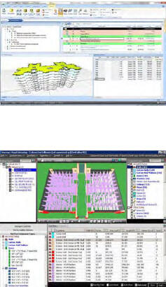
support DCAMM’s commissioning effort.) IFC quantity parameters and appropriate property set parameters may be supplied where model exchange uses IFCs among different BIM authoring tools. Third-party plug-ins that facilitate bi-directional IFC data exchange with Revit MEP, Revit Architecture and Revit Structure may be appropriate.
Responsibility: Responsibility goes to BIM Manager, Constructor, and GC Estimator.
Deliverable: Provide in “scheduled” format (grid or spreadsheet) quantity listings for windows, doors, fixtures, and finishes tied to corresponding spaces, categorized according to owner-preferred space categories. These additional OmniClass tables shall serve as a standardized QTO classification basis: Elements (Table 21) and Products (Table 23)
For early design, estimators may have approximate or historical costs by space function. OmniClass Tables 13 and 14 should be used:
- Spaces by Form (Table 14), Spaces by Function (Table 13)
Software: Revit Suite, VICO Office, Innovaya, BuildingExplorer, Navisworks
4 Sustainability, Energy, LEED
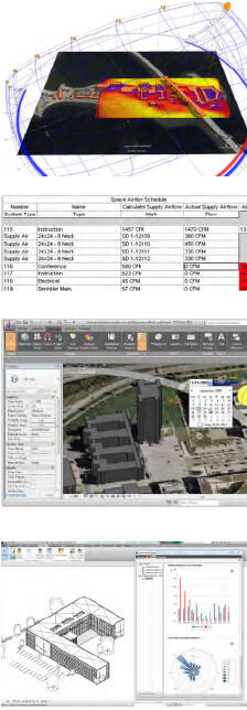
DCAMM requires BIM analysis to help achieve sustainable, resilience, and energy efficient designs on its projects.
4.1 Energy Modeling, Sun Studies, Day Lighting
Description: In this Use Case, the BIM is analyzed to improve day lighting in design, to understand sun shading needs and the balance between daylight and artificial lights to support space usefulness. Energy simulation, solar load analysis, daylight feasibility, sun and shadow studies, and thermal break representations are based on materials and other BIM data including geometry. In early design, these studies may be done simultaneously to support design options for interior visual comfort and task needs, window placement, direct sun and passive solar analysis in building placement, sun-shading features, and on site shadow studies for site DCAMM. The BIM is also used to quantify daylight luminance levels to support the documentation of the LEED IEQc8.1: Daylight and Views – Daylight.
The BIMxP will specify whether ASHRAE 140-2007 and/or ASHRAE 90.1-2007 (LEED Energy) standards are to be met.
If BIM is not used, then the rationale, process and software used shall be documented in the BIMxP.
Responsibility: Architecture team, mechanical engineer
Modeling Elements: (see reference documents)
The models shall be created to an LOD and quality required to perform an energy analysis for the phase and decision requirements of the project, per the BIM authoring software requirements and recommendations.
Design Teams shall utilize energy modeling and sustainable design software that extracts BIM data to the appropriate file format for the analysis tool.
Deliverable: Calculations, data and visualization of study analysis to be used in BIM based reviews, and design option activities.
Software: Concept design – Green Building Studio Energy Analysis, Ecotect, and Vasari, EcoDesigner STAR, and energy analysis tools based upon Energy Plus-DOE 2, IES.
References:
EcoDesignerSTAR
4.2 Existing Building – Rapid Energy Modeling
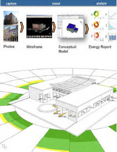
Description: Rapid Energy Modeling (REM) is a streamlined process for simplified simulation that quickly and with minimal data from existing building conditions develops an energy analysis. Additional process information required will include location, orientation, building geometry, and internal systems. Material assignments and space representations must be executed in accordance with BIM authoring software requirements and recommendations. Optimizing a building’s performance requires incorporating all those variables into design and operations along with weather data and building science. BIM authoring software that support rapid energy modeling will indicate approximations and “slack” as is appropriate to early design and lower levels of model development while still permitting energy modeling results useful to DCAMM.
Software: Sketch-up Energy Modeler – Sefaira, Autodesk Revit, IES
References:
Streamlining Energy Analysis of Existing Buildings with Rapid Energy Modeling
EcoDesignerSTAR
4.3 Mechanical Analysis
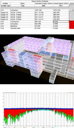
Description: Virtual testing and balancing of the design model to support sustainable building systems design and analysis, calculate native heating and cooling analysis that is built into the MEP software or exported using gbXML to an external analysis application such as eQuest, Trane/Trace, or DOE or EnergyPlus based analysis programs.
Responsibility: Mechanical Engineer
Model Elements: Room data can be read from the linked architectural model to create mechanical spaces (each space is the same as the room in the architectural model). Multiple spaces are joined to create zones. This data can be used to calculate native heating and cooling analysis that is built into the MEP software or exported using gbXML to an external analysis application such as eQuest, Trane/Trace, or DOE based analysis programs.
All airflows can be checked for load balance to the terminal box and back to the air-handling units. When internal spaces are defined, they shall be modeled with internal environment parameters for early MEP design.
Software: The software (eQuest, Trane/Trace, or DOE based analysis programs) used for this activity shall be identified in the BIMxP, IES.
References: Teams should check with MEP modeling software developers for additional information.
4.4 LEED Credit and Certification Reporting
Description: This Use Case relies on specs and BIM to identify, quantify, and cross-reference materials supporting LEED credits. LEED credits for design will be identified in the BIMxP.
Responsibility: Responsibility goes to the Architecture team, LEED specifier and others, based upon LEED credits.

Model Elements: Determine based upon LEED category and credits.
- Recycled percentage of materials for building elements (MR Credit 4.1)
- Calculations for roof pitch and rainfall
- Material location
Leadership in Energy and Environmental Design (LEED) evaluates green building criteria in five major categories: site design, indoor environmental quality, and the efficient use of energy, materials, and water.
Deliverables: Deliverables will include images, documentation, and reports as evidence of conformance for LEED certification
Software: Revit Architecture, Energy software – EcoDesigner STAR, E-Specs, Ecotect, GBStudio, IES
4.5 Lighting Analysis
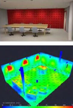
Description: This Use Case has two objectives: LEED compliance and energy performance and comfort. It relies on specs and BIM to identify and cross-reference materials and performance supporting LEED credits. LEED credits for design will be identified in the BIMxP.
Analysis also supports review for lighting comfort levels and usefulness.
Responsibility: Architecture team, specifier, and others, based upon LEED credits
Model Elements: Determined, based upon analysis use and LEED credits.
Deliverables: Deliverables will include images, documentation, and reports as evidence of conformance for LEED certification
Software: Revit Architecture, Energy software such as EcoDesigner STAR, E-Specs, Ecotect, GBStudio, IES
Data requirements are software analysis specific.
4.6 Systems Analysis
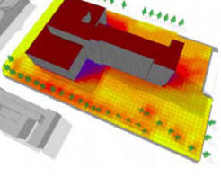
Description: BIM is used to capture the building geometry and characteristics needed to conduct aspects of energy performance analysis and support contracting processes. Use BIM to assess building performance, prioritize investments, and evaluate proposals to help reduce operational costs, conserve energy, reduce water consumption, and improve building air quality. The goal is to increase building performance and minimize energy consumption, water and wastewater infrastructure demands, improve air quality, and create a smaller overall carbon footprint.
Responsibility: The design and engineering team will continually monitor the progress from performance specification to design alternatives, identification of final solution and procurement to assure that the system installed meets the performance specifications and desired solution.
Model Elements:
- Building shell with energy data used in analysis and options modeling
Deliverables: A series of analysis reports identifying the options and the optimum solution for energy reduction. BIM model to be used as a basis of project execution and documentation.
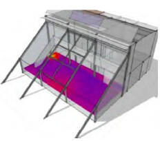
Software: Revit Architecture, Green Building Studio, EnergyPlus, Ecotect, IES, EcoDesigner.
5 Design, Constructability Reviews and Coordination
BIM efficiencies can be maintained or lost during construction handover. DCAMM requires the design and construction teams to work in a Lean manner to maximize BIM use, communication, and coordination. The following BIM Uses support this project phase.
5.1 BIM Based Progress Meetings, Reviews – “Big Room”
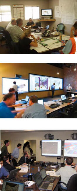
Description: The purpose of these reviews is to minimize misinformation between team members, to reduce paper-based communication, and to focus attention on design decisions at hand. The design or constructor team will utilize live model manipulation, saved views, and other electronic graphics to support problem solving and decision support.
Model Manipulation and Visualization: There should be a “designated driver” available for meetings. This person should be familiar with BIM presentations, and is responsible for setting up the model and saved views prior to the meeting.
Photorealistic and texture mapped model views are not required unless necessary for specific reviews. A working level of flat shade and shadow from BIM authoring tools is typically used.
BIG-Room –The current prime on a project is responsible for BIG Room set-up. The BIG-Room location(s) and responsibility during the phases will be identified in the BIMxP. DCAMM will make available a conference room and single projection capability on an agreed upon schedule. DCAMM may provide a space near the construction site for these meetings on a project-by-project basis. The constructor will be responsible for equipment and space for BIM in field use.
- Tablets supporting model use and review for field inspections and walkthroughs will be provided by the contractor.
- Web Meetings, software, and procedures will be organized and tested by the BIM Managers as part of project set-up.
Access to BIM Server
- Instructions, security access, and training for DCAMM PM and other stakeholders needing access to the model will be provided by the BIM Manager team.
Responsibility: AE, CM/GC, and sub-trades – BIM Managers and Coordinators
Deliverables: Design Coordination Reviews, Constructability Reviews, Shop Drawings, Construction Documents, Energy and Performance Reviews, Change Management Reports, Cost Estimates, Value Analysis Reports, and others as defined in BIMxP.
Software: Navisworks, VEO, Vico Office, Tekla, BIMsite, BIM360 or others as specified in the BIMxP
5.2 Digital Details, Mock-ups
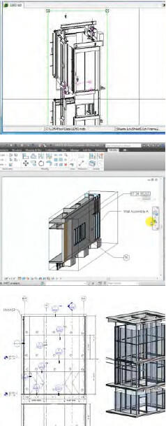
Description: It is cost effective for the project, and improves the discussion and understanding of construction for the design team to create digital mock-ups of elements in the project that are unique, require complete stakeholder understanding, or team consideration, for constructability meetings and value engineering. DCAMM supports the inclusion of 3D views and details in construction documents to support field understanding of the project.
Responsibility: The design team with DCAMM and the CM will determine when digital mock-ups are in the interest of the project. These will be documented in the BIMxP. It may be appropriate for trade sub-contractors to work with the CM, Constructor, and A/E to create the digital mock-ups as part of the shop drawing process. This will be documented in the BIMxP.
The BIM Manager will be responsible for the integration of any digital mock-ups into the integrated models for construction drawings
Model Elements: Some specific design elements that benefit from digital mock-ups are facades including curtain wall assemblies, parapets, shading, solar devices, mechanical spaces, shafts and elevators, material and building element interfaces and connections, way finding signage, and blind spot identification.
Deliverables: Images, views, sub-models, integrated model sections, per the mock-up creation and views to be integrated into construction drawings as appropriate will constitute deliverables for this Use Case. CAD details are to be incorporated into the permitted construction set, and models are to include sufficient details as they relate to trade coordination and model-based shop drawings.
Software: Revit, MEP software, AutoCAD, Revit, Tekla, other applications identified in the BIMxP
5.3 Scheduling – 4D Modeling and Logistics
Description: Construction coordination model supporting Look-Ahead, construction phasing, construction material movement, labor sequencing, site planning for material delivery, loading/unloading, staging, and storage. Supports team communication, conflict resolution, training, and schedule compliance.
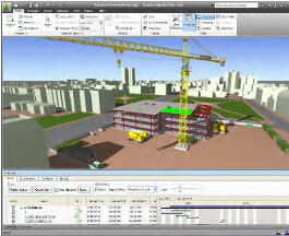
Responsibility: CM/GC, Scheduler, Construction BIM Manager
Recommended Elements for 3D Details: All project models as they relate to the trade planned scope of work. Site area required for material staging. Equipment as needed to show sequencing. (See list provided in BIM Use 5.4)
Deliverables: Updated 4D models as the project progresses, with updating, reporting, and delivery as set in BIMxP
Software: Synchro, Navisworks, Timeliner, Vico Control, VEO
5.4 Site Safety Review
Description: Integrating the project site logistics, materials and equipment use, vehicles, with load and delivery planning schedule data with BIM provides a means to see, prevent, and resolve conflicts. This information is easier to communicate In BIM. The model can be used for approvals, reviews, and safety training.
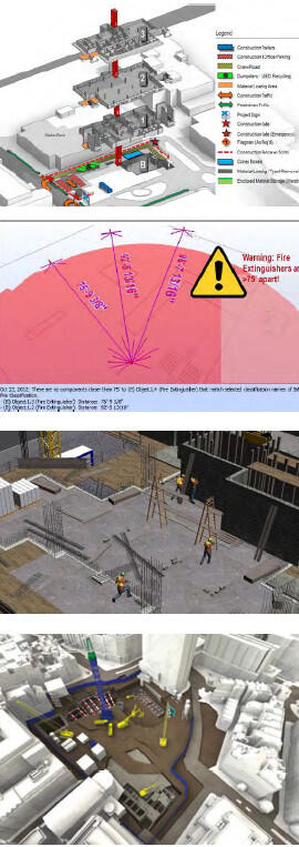
Responsibility: CM/GC, Scheduler, Construction BIM Manager
Recommended Elements for Model: Modeled elements for this Use Case include the site, temporary access roads, adjacent roads, building shell(s), cranes, trucks, materials storage areas, staging areas, necessary clearances/access, vehicular traffic and pedestrian flows, protected/off limit areas, protection measures, and adjacency restrictions.
- Landmarks including Fence, Sheds/ scaffolds, Hoist, Crane, Foundation/ Excavation, Transit, etc.
- Site in question, Lot lines / site boundary lines & Adjacent Building within 20’ of the lot line.
- Adjoining building exits to the street and any common yards with in 20’-0” of the building under construction
- Cross street – if applicable
- Sidewalks - provide widths of all roadways and number of lanes, sidewalks
- Lot Dims/ Meets & Bounds
- Vehicular traffic flow on and off the site
- Guard booth /watch person calculations
- Temporary walkways
- Show the site enclosed with a construction fence if required
- Truck and personnel gates
- Fire department access
- True North presented
- Submittal elevations based off buildings ground floor, not sea level
- Location of ramp with means of egress for the works
- All structures on the site
- Show protection of pedestrians, egress & adjoining property
- Storage of Materials
- Temp electrical and water, sanitary facilities
- Chutes
- Crane location and maximum / minimum radius of the boom & the radius of the counter weight. If a tower crane is used, provide weathervane radius
- Standpipe
- Containers
- Sidewalk shed if required
- Show all existing services (i.e. waste, gas, electric, sewer, signs, HYD, lights, Muni-meters) Fire hydrant and cutouts at construction fence
- Signs, signage for the gate scaffolding and sidewalk sheds
- Siamese and manual release value with details
Construction:
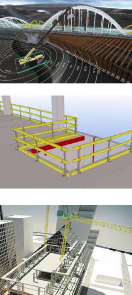
- Height of building and setbacks for adjoining buildings and their setbacks within 20’ of the lot line, in feet and stories.
- Adjoining Property Protection
- Extent, sequence and means of demolition.
- All Bracing and Shoring necessary
- Horizontal safety on floors
- Vertical Safety on floors
- Types of roof protection
- Typical Adjacent Window Protection
- Show protection at all foundation exposures with railings and fences
- Show pads for cranes, elevator pits, and hoists
Excavation / Foundation
- All excavation must have ramps with a ratio of 1:4 to be used as egress: show second means of egress for workers
- Show protection of utility poles, trees, etc.
- Show gates with flagmen at each side and project signage.
- Show protection at all excavations, including railing and fencing
Deliverables: Deliverables include site views, animations, construction and material placement sequences, logistics plans in .pdf format as the project progresses, a 4D site logistics and security model, delivery schedules, and schedule updates.
Software: Software will include Synchro, Navisworks Timeliner, Vico Control or other as specified in BIMxP.
5.5 In Field – Construction Layout
Description: BIM is used as a basis for laser guided field layout of walls and building elements. BIM supports better construction layout. As components are fabricated to the model, it is imperative that the layout be per the model to avoid field construction issues. Survey or layout points are taken from the model and loaded into robotic total stations for layout.
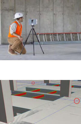
Conversely, survey/layout points are captured in the field during construction and round-tripped back to the model for proactive validation/quality control. When this workflow is closely followed, the BIM is self-documenting and constitutes a sound basis for the As-built (Record) BIM.
NOTE: to enable correct layout/verification, the team must keep the federated BIM accurate, complete, and up to date. 2D drawing documents must flow from the model and dimensions must remain associative.
Responsibility: CM, Constructor and sub-trades have this responsibility. The BIM Manager must keep the model federated while the GC BIM Manager provides model updates. It is the responsibility of the architecture and structural team to model to tolerances supporting BIM-based field layout.
Recommended Elements: Project features that must be modeled to support this Use Case include excavation and grading, foundations and vertical concrete (formwork, anchor bolts, penetrations), structural, embeds, MEP system distribution anchorage, wall layout, penetrations, stairs, exterior envelope, equipment anchorage, flatwork, and site utilities.
Deliverables: XYZ survey/layout point files for exchange with field layout equipment.
Software: AutoCAD, AutoCAD Civil 3D, Tekla, specified in BIMxP.
5.6 Laser Scanning - Construction Phase
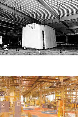
Description: 3D laser scanning performed during construction captures as-built work. This aids the team in change management, captures newly built conditions prior to being covered and closed to view, and later will aid facilities operations in reliably locating systems components with a high degree of accuracy. Laser scans may also provide detailed information for subsequent renovations.
Coordination for Survey Points: Coordination between the DCAMM survey contractor, the laser scanning team, and the BIM Manager is necessary to determine the use of existing or the positioning of new survey points per DCAMM requirements.
Responsibility: Responsibility is shared by the CM, Constructor, or the DCAMM survey team, and/or may be performed by subcontract to a third party specialist.
Recommended Elements: Prior to closing walls and ceilings, in-wall and interstitial spaces can be captured along with major MEP equipment locations and paths. At the Site, exposed existing utilities, new hook-ups and new utilities can be located.
Deliverables: Registered/rotated/elevated 3D point clouds conforming to the defined coordinate system as determined in the BIMxP. The organization of point clouds will be determined based on overall aggregated file size and the teams’ capability to handle such files, similar to how BIM content is aggregated or parceled for use by the project team and owner during the facility lifecycle.
Software: Faro Scene, Leica Cyclone, Trimble Realworks
5.7 Pre-Fabrication Building Components
Description: This BIM Use Case includes modeling the proposed building components with a focus on visualizing and simulating the logistics of their placement in a new or existing building, as well as the logistics of maintenance, repair and eventual replacement in situ. This Use Case goes beyond fabrication and shop drawing coordination.
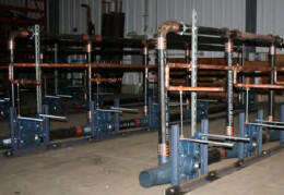
The building industry is trending toward prefabrication of ever larger and more complex building components in order to exercise rigorous quality control over the finished product, to eliminate weather related delays, to make use of semi-stationary fabrication equipment that cannot be brought to a building site, and to reduce costs. This Use Case includes simulations of onsite placement and maneuverability, and visualizations to support decisions as to how best to modularize and maximize pre-fabricated building components.
Responsibility: Constructor, CM, sub-contractors, manufacturers.
Deliverables: Deliverables include schematics and animation sequences of prefabricated building components being transported, placed onsite, and installed.
Software: Revit Software Suite and other specialty software as required per BIMxP.
6 Documentation, Drawings, and Specs
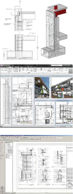
It is a DCAMM requirement that drawings and construction sets are derived from the model. The following BIM Uses support BIM use for more coordinated documentation during design and for record models at project turnover.
6.1 Construction Drawing Production
Description: Construction Documents (CDs) are derived from the model. Views are automatically generated in the BIM file by the authoring software. Assuming no software errors, this automatic generation benefits the team’s coordination and development of the CDs because the unity of the model provides consistency of construction document views. The documents so generated include plans, exterior elevations, interior elevations, sections, and reflected ceiling plans. Schedules and legends generated from the model will be as sound as the inputted data. 3D detailing and color-coding are enhancements that improve communication.
2D Details: Details derived from the model are better coordinated than generic 2D details created in the traditional way by documenting a mental visualization effort. Whenever possible, the details shall use the model as a basis for detail drawings. These details will be created over the active 3D geometry. 3D axonometric and perspective details are recommended in addition to standard 2D details because they often capture and convey more information than 2D views alone, in particular, the relationships among sections and elevations.
CD Generation: Construction Documents (CDs) are not the driver of the BIM process, but rather a required output at the end of the design process. The final CD set should be developed from a model that has gone through the various review processes and quality control checks. These include visual checking by the modelers, clash detection by the design team and CM, and model checking for quality in a model-checking program.
Responsibility: A/E, Discipline Model Coordinators, sub-trades for shop drawings, specifier, and other model authors all have this responsibility
Deliverables: Deliverables will be per DCAMM Drawing and Publishing requirements in the BIM Guidelines.
Software: BIM Authoring and discipline tools, Revit suite, and other tools identified in the BIMxP.
6.2 Shop Drawing Coordination
Description: Detailed shop drawings for fabrication and construction are derived from the discipline specific design intent model. Coordination among the federated models produced by the A/E, constructor, and the job shop fabricator is required. Shop drawing coordination is at a fine level of detail. Moreover, shop drawings are governed and guided by equipment and tooling that is available to fabricate the items represented in the BIM, its shop models, and their derived drawings. These shop drawings must be consistent with one another (fully coordinated) and frequently carry or imply sequencing, forming, folding, and attachment, fit and finish information. 3D views should be incorporated into the shop drawings for better communication.
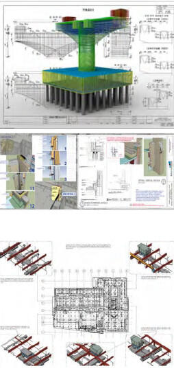
Responsibility: Constructor BIM Manager and sub-contracted shop fabricators are the responsible participants.
Deliverables: Shop drawings may be supplanted by a “shop model,” from which G-code can be generated to control machines that cut, place, fold, bend, weld, and otherwise create building elements, components, and parts according to the design intent model. On projects where this level of workflow automation is, not employed, standard shop drawings must still flow from a shop model that is derived from the BIM and supplemented by 3D views.
Software: Suitable software for transforming design intent models into appropriately detailed shop models is required.
6.3 As-Built Models
Description of As-Built Model: A Navisworks file incorporating shop models and drawings and as-built conditions is more detailed than the record (.rvt) model. For example, the as-built would show hanger locations while the record model may not. This model may be used during construction in the field using mobile BIM software.
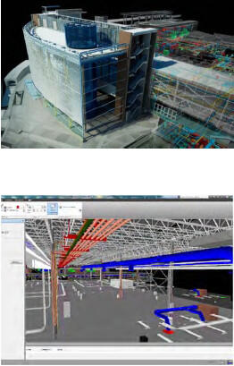
Responsibility: The Constructor’s BIM Manager, Design BIM Manager, Commissioning Agent, and the DCAMM BIM Manager have this responsibility.
Deliverables: Deliverables include the Navisworks file; data are represented in the BIM, in systems and equipment test specifications, and in test results. Some of these test specifications and/or test results may be linked to graphic BIM elements, while others may be in the form of standard Commissioning documents external to the BIM. The BIMxP (Section 5. Model Element Worksheet) in coordination with the commissioning agent’s contract will specify which information is found where.
Commissioning of the BIM itself may be required according to specifications found in the BIMxP. If so, then documents listing all software and associated add-ons, add-ins, plug-ins, stock and custom object libraries, and other application-supporting modules that have been used in producing the BIM, shall be provided with specific version and software “build” numbers. Furthermore, if the BIM itself is to be commissioned, then the report produced by a final model-checking run at the point of handover shall be submitted to DCAMM. The BIMxP in coordination with the commissioning agent’s contract will specify the aspects of the BIM to be checked in terms of rules and rule sets so the results are fact-based, repeatable, verifiable, and documented. The report will include a statement of which rule sets correspond to checks for which Use Cases.
Software: Software will include BIM authoring software, external but linked databases, and Navisworks. EcoDomus and Solibri Model Checker may be used to support review prior to handover. Rule sets used in model checking will be shared among team members and exchanged with DCAMM for team-wide validation.
6.4 Data Normalization
Description: The BIM Managers, the DCAMM Project Manager and the commissioning agent will supervise the creation and review of information required by DCAMM. Normalized data in the sense applied to BIMs is derivative from, but less stringent than, that formally defined by E.F. Codd and successors as the normal forms a relational database may achieve.
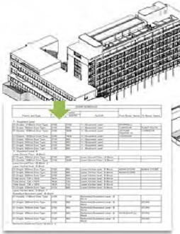
Spreadsheet practitioners will be familiar with the four or five different ways of naming and abbreviating “conference room” and the various manipulations required finding all the conference rooms in a large project where multiple participants have different ways of naming them, and drawings and spreadsheets seem to collect all the variations. This situation can lead to errors in counting and tracking, and ultimately unreliable project information.
As applied in the BIM context, normalized data describes data that has consistent field names, consistently spelled data values, and uniformly established data types. Among other things, this requires a rigorous enforcement of room name spelling and room type spelling, as well as equipment naming and typing. For reliable and automated data exchanges, and internal to the BIM, there are unique identifiers that the software uses to manipulate the objects we know by name and/or by particular instances.
“Data cleanup” is essentially the task of preparing data to be usable by BIM systems in a consistent manner to provide consistent reports and analyses with minimum querying effort. Data cleanup is frequently a time consuming effort that cannot be avoided. Spreadsheets permit data entry inconsistencies that databases do not. A good normalizing step can be to take spreadsheet data and import it to an SQL or MS Access database to assist in detecting some kinds of data inconsistencies.
The basic data standards include:
OmniClass Table 13, UniFormat, MasterFormat, and the DCAMM data fields required in commissioning. COBie data may also be required. If COBie data are delivered, the model must be developed to support COBie spreadsheet export.
Responsibility falls to the Design BIM Manager, Constructor’s BIM Manager, Commissioning agent, DCAMM project manager, with DCAMM IT database expertise oversight.
Deliverables include the BIM Record model with normalized data following the DCAMM standards.
6.5 As-Build CAD Drawings for Handover
Description: DCAMM may require As-Built CAD drawings of all floor plans from the Record Model. These drawings will be used by DCAMM to be integrated with the CMMS and New CAMIS (Tririga) applications used by DCAMM. DCAMM BIM Manager will specify the AutoCAD version for saving the files.
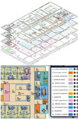
Responsibility: With the design team, the constructor BIM Manager is responsible for developing the As-Built information. The CAD files saved from the model are the responsibility of this documentation team. It is to be documented in the BIMxP.
Model Elements:
The CAD files will show traditional building elements for floor plans.
- Wall, doors, and window elements, stairs, core, elevators
- Major equipment and data
- Areas and room spaces with identifying data
- Room name and number
- OmniClass functional use
- Public and secure spaces
- Leased and tenant spaces
- Measurement
All updated floor plans with data for each space and major equipment. Verified column grid and survey points.
7 Commissioning and Handover
7.1 Virtual Handover (Record Model)
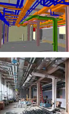
Description: The virtual handover (record model) is the design intent model, updated with as-built locations for building elements within the model. In the DCAMM context, this will be a .rvt file. This updated model is submitted to DCAMM and reviewed for product data requirements, model versioning, and integration into the DCAMM environment. Upon substantial completion, the design team should finalize this record model for handoff to DCAMM as part of the commissioning process.
Commissioning of the BIM itself may be required according to specifications found in the BIMxP. If so, then documents listing all software and associated add-ons, add-ins, plug-ins, stock and custom object libraries, and other application-supporting modules that have been used in producing the BIM, shall be provided, with specific version and software “build” numbers. Furthermore, if the BIM itself is to be commissioned, then the report produced by a final model-checking run at the point of handover shall be submitted. The BIMxP in coordination with the commissioning agent’s contract will specify the aspects of the BIM to be checked in terms of rules and rule sets so the results are fact-based, repeatable, verifiable, and documented. Rule sets used in checking the model shall be agreed upon by the project team and specified as part of the BIMxP.
Responsibility: The design and constructor BIM Managers will work together to assure that the record model contains the necessary building element updates, product, space, and FM data. The model links should be unbroken.
7.2 COBIE Data Set
Note: If COBie is not required on the project, the team should use DCAMM equipment list to determine attribute needed for objects and elements.
Description: COBie (Construction Operations Building Information Exchange) is a vendor-neutral flexible data specification that indicates how to format design and construction data so that they can be consumed by other facility software. COBie data includes all the information necessary to operate the building properly. Much of this, but not all, will be found in the BIM. COBie provides an extensible framework that describes both the process of collecting and validating data, and the datasets that contain required data. Commissioning procedures use some of the same data as COBie, as input to or the basis of performance and compliance testing. The spreadsheet is only one view of COBie data. The spreadsheet view of COBie data can flexibly be expanded or streamlined as necessary to meet DCAMM’s requirements.
Available files:
- DCAMM Revit template file may be used to support the COBie BIM Use by directly extracting COBie data from the Revit file.
- Third party software may extract COBie data from an IFC BIM exported from Revit.
DCAMM Revit template file may be used to support the COBie BIM Use by directly extracting COBie data from the Revit file.
Third party software may extract COBie data from an IFC BIM exported from Revit.
Project Set-Up: The COBie implementation process should begin before an experienced AE team starts project modeling. As part of the project set-up, DCAMM, the team, and the BIM Manager need to determine a clear set of requirements for the modelers in order to reduce the amount of downstream rework (waste) in the project lifecycle. Beginning with the end in mind, the BIM will be structured to carry the required data.
- The DCAMM team shall review the project scope of work to determine the COBie data to be collected. This will be based upon DCAMM’s need for data to operate the facility, not primarily on modeling convenience.
- The A/E BIM Manager will work with the DCAMM BIM Manager to update the Revit template for the project
- The required data will be found in the BIMxP.
Data requirements:
- Object Attributes (metadata) for Type, Component, System, Space, Facility, Floor
- OmniClass Use: DCAMM is transitioning to OmniClass. OmniClass will be used in BIM: Table 23 – Products (objects), Table 21- Elements, including designed elements (systems), and Table 13 – Spaces by Function (locations).
- Documentation Categories for Type, Component, System, Space, Facility, Floor the COBie framework requires that delivered documents are attached (linked) to asset types, components, systems, etc. The documents required for a specific equipment category can be defined by using OmniClass.
- Example: the documents required for a chiller (23-33 21 00) are Product Datasheet, Photograph, Test Report, Warranty Information, O&M Manual, EHS Information, Spare Parts and Supply List (and possibly others).
- Example: A lighting fixture (23-35 47 00) only needs Product Datasheet, Photograph, Spare Parts and Supply List. In both examples, COBie is flexible enough to allow additional or fewer document types to be associated to a specific asset type according to DCAMM’s needs. It is recommended to keep the defaults.
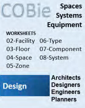
Most of current online project management systems allow collecting documentation and linking it to equipment records. Owners can also use specialized software applications to verify the availability of the documents provided by the project team.
- Data Collection Rules: As part of project scheduling look-ahead, the team will identify milestones and the requirements for each milestone
Design Phase:
- Facility and Floors are defined
- Spaces should be classified using OmniClass and Net Area is provided (Gross Area is generated by the BIM authoring application)
- Zones should have Categories assigned
- Types should have Name, Category (OmniClass), Description, Asset Type
- Components should have Name, Description, Type and Space
- Systems should have Name, Category (OmniClass), Components
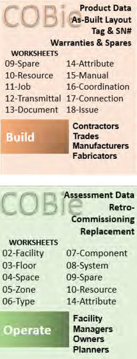
Construction Phase:
- Type information is updated by providing Manufacturer, Model Number, Warranty information (Parts and Labor and Duration), Replacement Cost
- Component information is updated by providing Serial Number, Installation Date, Warranty Start Date, and optionally Tag Number or Barcode. Installation Date for major equipment will be the Finish Date of the corresponding schedule activity.
- Spare parts are provided for Types
- Attributes are provided for Types and Components
Commissioning Phase and Handover:
- Test reports and other documents are assigned (uploaded) to corresponding BIM objects (Types, Components, Spaces, Facility)
- Attribute values are corrected based on real measurements
There are off-the-shelf software tools that allow verifying that data are provided correctly at the specific milestone.
Naming Conventions
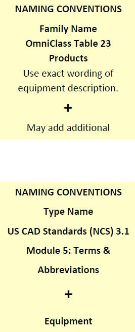
- DCAMM requires the use of OmniClass as the classification standard and the U.S. National CAD Standard as a guide. To ensure use of the latest version of OmniClass names and numeric codes as the classification standard, see OmniClass.org and BIMxP.
OmniClass Table 23 – Products is used to code and classify Equipment families digitally.
Example: 23-27 21 11 is the OmniClass designation for equipment type Axial Flow Compressors. Table 21 – Elements is used to code and classify Equipment Systems and Zones digitally.
Example: 21-51 31 11 17 is the digital code for equipment system named Domestic Water Distribution
Example Procedure: (This example makes use of a third party spreadsheet that is a crosswalk lookup of OmniClass classification numbers and equipment type headings to BIM abbreviations.) To establish Family, Type and Instance names for Variable Air Volume (VAV) Box, look it up in the “OmniClass and Abbreviations” spreadsheet to find the corresponding OmniClass number and title. It will be “23-33 41 17 13 Variable Air Volume Terminal Unit”.
Therefore, Family Name will be “Variable Air Volume Terminal Unit.”
The Type Name is composed of the abbreviation and operation description.
Example: where Abbreviation =“VAV” and Operation description
=“Reheat, 6 inch”, the Type Name =”VAV Reheat, 6 inch.”
The Instance Name is composed of the abbreviation and a unique ID appended, i.e. “VAV-001,” “VAV-002,” and so on.
In addition to specifying names for required types and components, type and component descriptions must be provided. There is no need to enter a description for every lighting fixture instance. Rather, type description is sufficient, which is required for COBie. Type description should be specific to that equipment type and be helpful for O&M personnel to see quickly, without going through the list of extended attributes, i.e. “Single-duct, digital controls.” Instance description should include unique details of the particular instance that could be helpful for O&M, i.e. “3 feet from the door 301, above the duct.” The BIMxP will specify what DCAMM requires for its O&M personnel.
Examples for naming other object types:
| Family Name | Type Name | Type Description | Instance Name | Instance Description |
|---|---|---|---|---|
| Supply AirVentilation Diffusers | SA DIFF 24” Face8 Connection | Round Coned Diffuser | SA DIFF RC-1 | Supply Air Diffuser Type RC-1 |
| Volume Control Damper Round | VD Standard Round Supply | Round VolumeDamper on Supply Ducts | VD RND SPLY-2 | Round Volume Damper on Supply Ducts |
| Transformer Liquid Filled Substation | XFMR 500xVA, 4.8kV | Transformer, 4.8 kV – 480/277V | XFMR T-MSC-1 | |
| Electrical Panelboard | PB 208/120V, 225A | Panelboard 208VMLO Surface | PB EL1A | |
| Electrical Receptacle Duplex | ELEC RECPT GFCI Duplex | Receptacle | ELEC RECPT-1 | |
| Lighting Fixtures | LTNG FIXT 24” 2’x2’ Indirect | 2-Lamp Lighting Fixture, 277V | LF-001 | |
| Gate Valve | GTV Gate Valve1” | Gate Valve | GTV-040 |
System Nomenclature
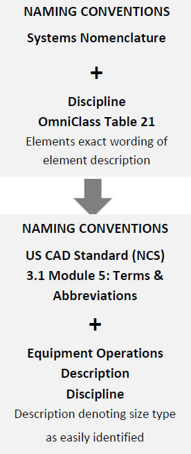
A combination of the industry standard nomenclature OmniClass Table 21 – Elements, the U.S. National CAD Standards (NCS) 3.1 Module 5, NBIMS, and other standards to name systems is illustrated below.
Example: Supply Air System for Air Handling Unit (AHU) D-1
OmniClass Table 21 21-04 30 60 10 Air Supply + Discipline (Mechanical) + AHU + Description “D1” = AHU-D1 = System Name “Mechanical Supply Air AHU-D1”
For systems that are not directly connected to a piece of equipment, follow this convention:
Example: Return Air RG-1 2nd Floor 214A Office
Industry Discipline – OmniClass Table 21 + Equipment Operation Description (as above) + Floor and DCAMM Room Name and Numbering Convention (OmniClass Table 13 + Room Numbering Protocol in Referenced Standards)
Zone Nomenclature
A combination of various standards to name zones is illustrated below:
Example- HVAC Zone associated with VAV Box D01 serving offices 100-101-102
NCS 3.1 Module 5 – Abbreviation for Air Handling Unit- VAV –
Description denoting size/type easily identified “D01”, + DCAMM Room Names and Numbers contained in the zone 99, 100, 101 = ZONE NAME – VAV-D01 Offices 99, 100, 101
Available files:
- Excel file for basic required attributes
- Another source of information for object attributes is the COBie Guide
Deliverables: Based upon the agreed upon assets to be defined in COBie, the team will populate the COBie worksheets per the schedule defined in the BIMxP.
Software: Software is the model authoring Revit suite, including Navisworks; EcoDomus and Solibri can check model quality and COBie Data.
7.3 Commissioning
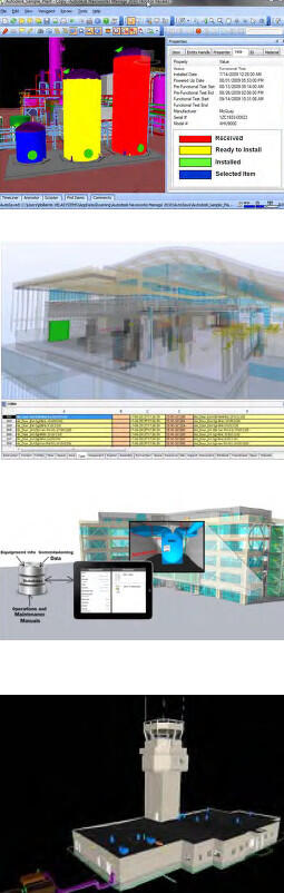
Commissioning is an important opportunity to develop a facility BIM. Early coordination meetings will help update data requirements and determine whether a mobile BIM version will be used to collect data or data will be entered into the BIM during As-Built updates. Early involvement of a Commissioning Agent (Cx) can identify data collection synergies and may reduce data collection costs.
Description: Commissioning is a systematic process of verifying that all building systems perform interactively according to the design intent and the owner’s operational needs. This is achieved by actual verification of performance. Commissioning starts in the design phase and extends through the post-occupancy phase of the project.
Purpose: The objective of commissioning is to provide documented confirmation that the facility will fulfill the required functional and performance requirements. Commissioning can also provide information about systems’ actual performance under building-occupied conditions.
Responsible Parties: Responsibility: The Commissioning Agent is involved throughout the project from the design through post occupancy phase. The agent will work with the BIM Managers to identify the objects and attributes supporting equipment commissioning. A report supplied by DCAMM and COBie spreadsheet will be created to support the commissioning process.
The Commissioning agent will meet with the PM, facility manager, IT, communications, and major building systems subcontractors to determine any updates to the data requirements, and to share their design and fabrication data as relevant to commissioning.
Designer Responsibilities: The project design team is responsible for two aspects of asset management that are included in the BIM documents: identification of geolocation codes (and room numbers) in the models and identification of asset tag numbers in the record model and on as-built plans. DCAMM’s room numbers for all projects are supplied by the A/E and/or Project Manager and/or FM. Asset numbers generated through the NEW CAMIS (Tririga) will likewise be provided to the Cx.
Asset Management Data Collection: DCAMM uses Tririga as its enterprise asset management (EAM) system. The Commissioning agent will verify the New CAMIS Tririga version at Commissioning commencement. Collection of data for assets is required for all equipment and systems as defined in the EAM on-boarding documentation available from DCAMM. The Standard Operating Procedures will include spreadsheets for all DCAMM asset classifications, attribute information required per asset type, and tagging requirements for assets included in the EAM system. The following is a list of minimum information that must be provided for asset data:
- Name plate data
- O & M manuals
- Preventative maintenance requirements including frequency and time to complete
- Parts list and parts list per job plan (PM requirements)
- Asset attributes
While the DCAMM classifications are based on OmniClass standards, they are not identical. Therefore, it is important that the DCAMM standards be followed when reporting asset data. Asset tagging, which is performed by the Commissioning Agent, will be done using DCAMM supplied tags.
Deliverables: Record Model updated with DCAMM data requirements on major assets and spaces and project construction documentation supporting the commissioning process
Software: Revit Suite and COBie Spreadsheet, EcoDomus, mobile BIM software, third party products supporting BIM data collection
7.4 Model Data Supporting Disaster Planning
Description: DCAMM may require BIM use and GIS data for Master Planning studies that include considerations for disaster planning. The A/E will consider options in BIM for disaster planning per DCAMM project requirements. For example, consider line-of-site, escape routes, security zones, blast areas, mitigating and/or required and setbacks, and their associated equipment. Crime Prevention Through Environmental Design - Response Enhanced Designs (CPTED-RED) options may be modeled in BIM.
BIM Data: Owners of public facilities need to provide first responders accurate facility information. BIM in combination with other organization and situation data can be used to support disaster response situations. This information is made available for disasters in multiple formats in various media including electronic (computer), cloud, paper, and via multiple locations, and access points.
Responsibility: Responsibility falls to the design BIM Manager, constructor BIM Manager, CPTED or other security consultant.
Model Elements: Site and Building elements are affected by the disaster options under consideration. These elements are to be documented in the BIMxP including custom objects for security setbacks, blasts, etc. Some objects will require LOD 300-350 data to support simulations. For example, wall assembly, window glass type, protective films, slab type and construction, and some fixed element types that can become projectiles are required for effective blast simulations.
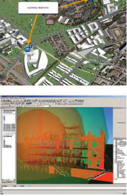
Deliverables: Deliverables include simulations, model views supporting design options during design and master planning, assumptions, and some degree of structural analysis.
Software: Revit suite, GIS, Navisworks, simulation software, custom objects
7.5 Model for Maintenance and Maintenance Training
Description: The models are used during commissioning, pre-occupation, and post-occupation to train staff on asset location, maintenance access, and maintenance procedures. This information can be developed into a mobile accessible package.
Responsibility: This is a joint responsibility between the commissioning agent, the facility manager, and constructor’s BIM manager. Additional sub-contractors may be required to integrate BIM, O&M, and facility data for facility management training. The training packages can be simulations, animations, accessible mobile models, and data.
Model Elements: Elements will be those required for maintenance training on major assets. In some circumstances additional detailed models of walk-in equipment may be developed to simulate, demonstrate, or schematically illustrate both normal and emergency lockout, shutdown, and startup procedures.
Deliverables: TBD. Third party software may be used to develop the training packages.
Software: Revit Suite, EcoDomus, BIM360, BIManywhere.
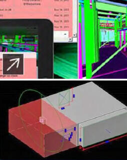
8 Facilities and Data Integration
8.1 Assessment Models
Description: BIM may be used in the field for efficient data collection. Mobile software supporting BIM shall be considered by the assessment team. The team will work with the DCAMM FM and BIM Manager to determine the BIM data requirements per the assessment scope of work and the in-field tools to be used.
Responsibility: Responsibility falls to a BIM capable assessment team, DCAMM FM, and the DCAMM BIM Manager.
Model Elements: Elements to be assessed will be defined by DCAMM. The team will utilize the element standards (UniFormat).
Deliverables: Data deliverables are the updated BIM, assessment report, and database for integration with New CAMIS (Tririga).
Software: Existing BIM, EcoDomus, BIM360, New CAMIS (Tririga) integration tool.
8.2 Space Planning – Move Management
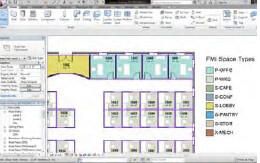
Description: The design and space planning team will utilize BIM and intelligent objects to manage space, occupancy and use.
Responsibility: Architecture BIM Manager and discipline team. DCAMM may be required to provide operational and space requirements, and existing plans and data.
Model Elements: Space planning team will utilize BIM to develop intelligent floor plans with functional space data, room numbering, and layouts to support move management.
Deliverables: Deliver a Revit model utilizing DCAMM BIM standards
Software: Revit Architecture, Trelligence Affinity, and other BIM space planning tools.
8.3 Security
Description: DCAMM may require BIM use for security studies on public and institutional, prisons, judicial, and health care facilities. The A/E will consider security options and simulation in BIM per DCAMM project requirements. For example at a site level, analyses of line-of-sight, escape routes, security zones, blast areas, and setbacks can be done with a BIM. Crime Prevention Through Environmental Design (CPTED) options may be modeled in BIM, often in conjunction with site studies. Security experts will recognize the relationship between this Use Case and those having to do with Resiliency Modeling (below) and business continuity, generally.
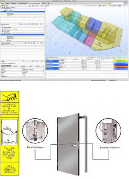
Security experts can use model-checking software to examine the relative locations of hazardous materials storage for security review of proximity, adjacency, synergy and reactivity. Emergency responding personnel can use appropriate models to “walk a building space” to identify hazards and threats, before entering a facility. Security personnel can use a fully accurate BIM to identify spaces where threats can potentially be cached, blast zones, direct kill zones, personnel loss and collateral damage, and other relationships of concern to security experts.
BIM Data: BIM spaces in combination with operational and situation data can be used to support security simulation and review for public buildings. Manufacturer objects for doors and security. This information and design options are made available for review by security groups.
Responsibility: Design BIM Manager, Constructor BIM Manager, Security and/or CPTED consultant.
Model Elements: Elements will include spaces with OmniClass functional space classifications and objects utilizing UniFormat as well as line-of-sight camera views for security stations; surveillance and access control cameras; and some materials defining sound, glass and/or film strength; and secure safety, emergency egress doors, safe zones, and law enforcement access pathways.
Deliverables: Deliverables include model views, animations, and simulations supporting security review. Solibri model checker may also be used to verify space, walk and run distances and times, and public ceiling space accessibility.
Software: Revit Suite, Navisworks, Solibri Model Checker, simulation, animation software.
8.4 CMMS and CAFM Data Model Integration
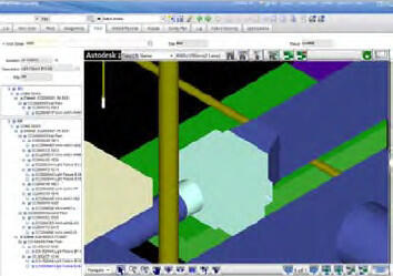
Description: DCAMM uses New CAMIS (IBM Tririga) for facilities management. DCAMM may require additional integration of Record model graphics and commissioning data with New CAMIS (IBM Tririga). DCAMM will provide the version and data requirements for New CAMIS integration.
Responsibility: BIM Manager or third party software integrator.
Model Elements: Elements will include floor plan elements, spaces, DCAMM room numbering, and equipment data per DCAMM facility management requirements. Globally Unique identifiers (GUID) will be provided from New CAMIS (Tririga) to support (future) round trip data flow.
Deliverables: The deliverables may be the integration of BIM graphics and data into the DCAMM New CAMIS (Tririga) facilities environment.
Software: Revit Architecture, New CAMIS (Tririga)
8.5 Resiliency Modeling

DCAMM Resiliency Definition: Resiliency is the ability of a system to withstand a major disruption within acceptable degradation parameters, recover within an acceptable time, and balance composite costs and risks. Resiliency requirements will vary according to the functional nature of a facility, structure, and/or equipment in relation to life safety concerns and business continuity requirements.
Description: Many DCAMM assets and properties are located in areas subject to naturally occurring environmental change. The mission of the assets are affected by data sets typically represented in GIS. These include population, transportation, weather and rainfall, storm surge, and other natural factors. Use of these datasets in a design mash-up and simulation greatly informs Master Planning and design options.
By utilizing BIM with this Cost-Benefit-Analysis (CBA) information, design options in BIM can help visualize these complex informational relationships supporting better design for sustainable and resilient assets.
From this macro perspective, BIM can be used for building materials, and construction techniques that help make design more resilient. These innovations can be modeled to determine the CBA and reduce the risk of innovation. Visualization and simulation can be used to support land use policies and help analyze first responder data and access prior to determining a final strategy.
Responsibility: The design team may choose to work with GIS professionals, state and local GIS data, and Master Planning information from DCAMM to gain a design-in-place perspective for design options.
Model Elements: Elements will include GIS data layers supporting a CBA, and asset elements with identified sustainable materials (attributes).
Deliverables: These will include BIMx or Navisworks animations and simulations for BIM and GIS, and third party products including Infraworks, ESRI modules for simulation, and models for exploration.
8.6 Building Automation Systems BAS Integration
Description: Integration of BIM graphics (2D & 3D) as spatial location points for building system sensor data. This is used for real time displays of system activities.
Responsibility: Responsibility for interfacing BIM data to building automation systems will be determined by the DCAMM BIM Manager, project managers and facility managers in consultation with DCAMM IT, the Study firm (if any is required), and the A/E firm providing design services.
Model Elements: The group having this responsibility (above) will determine which model elements will be required to support the intended Use Cases and will determine which BIM deliverables will be required to serve DCAMM’s needs, as well as the software to be used to satisfy DCAMM’s purposes.