16.1 Introduction
This chapter describes a variety of measures that can be used to lower vehicle speeds and redirect traffic flows. Speed management measures are physical road design elements intended to reduce vehicle speeds and improve driver attentiveness. Traffic diversion measures are the application of turn restrictions and other measures to redirect or restrict traffic flows. This chapter places a greater emphasis on speed management measures; however, traffic diversion strategies are also discussed.
Speed management incorporates three major categories of design measures:
- Vertical deflection – reduce vehicle speeds by creating a change in the height of the roadway
- Horizontal deflection – reduce vehicle speeds by creating a horizontal shift in the roadway which prevents a driver from traveling in a straight line
- Narrowing treatments – reduce or narrow the physical or apparent width of the roadway to encourage vehicles to slow down and reduce the crossing distance of the roadway in some cases
A major objective of speed management is to reinforce the desired target speed through the design of the facility, thereby self-enforcing the desired speed. The goal is to:
- Reduce the number of motorists exceeding the posted speed limit
- Reduce the speed of all motorists to the desired target speed
- Reduce the speed distribution (the difference between the maximum and minimum speeds of drivers)
- In some cases, to support the reduction of posted speed limits
The selection of appropriate target and design speeds is discussed further in Chapter 3. Speed management measures should help to achieve a more uniform speed distribution, which results in better predictability for crossing pedestrians and cross-road drivers. In many cases, speed management measures are also used to increase the attentiveness of drivers by signaling a change from the prevailing roadway conditions. Additional attentiveness is achieved through:
- Reduction of operating speeds
- Increase in recognition of other important users of the street, specifically, pedestrians, bicyclists, and motorists using on-street parking
- Heightened awareness of a need for safe driving behavior
- Elimination of inducements to aggressive and dangerous behavior (for example, reducing pavement width to stop vehicle overtaking)
16.2 Potential Benefits and Tradeoffs
When used in appropriate settings, the reduction in vehicle speeds obtained through speed management measures are intended to reduce both the frequency and severity of collisions. Further, speed management measures are also intended to increase driver attentiveness and reduce the likelihood of a collision.
Encouraging safe speeds is one of the five elements of the Safe System Approach and is critical in achieving the goal of zero fatalities on the roadway network. Reducing the kinetic energy transfer that occurs during a collision, which can be addressed through speed management, is a core tenet of the Safe Systems approach to traffic safety. Proactively managing the physical environment to reduce speeds with roadway design elements can minimize the severity of crashes.
Higher vehicle speeds can lead to crashes with large impact forces. Such forces increase the risk of a fatal and serious injury occurring, particularly if a vulnerable road user such as a pedestrian or bicyclist is involved in the collision. Humans have limited abilities to withstand the forces of these crashes. Reducing speeds is a tactic that serves to accommodate these vulnerabilities by curtailing impact forces and providing drivers with additional stopping time in conjunction with improved visibility.
Several studies support the correlation between reduced motor vehicle speed and reduced severity of collisions. As noted in Chapter 3, the risk of fatality and serious injury for pedestrians involved in a motor vehicle crash decreases with lower vehicle speeds, lessening from 77% at 40 mph, to 50% at 30 mph to 18% at 20 mph. For vehicle/pedestrian collisions, the severity of injuries increases sharply as vehicle speed increases, as illustrated in Figure 16-1. Speed management measures can improve safety and comfort for pedestrians by:
- Reducing crosswalk distances, and the extent of pedestrian/motor vehicle conflict
- Reducing motor vehicle speeds, their stopping distances, and the severity of pedestrian/motor vehicle conflicts
- Increasing the attentiveness of motor vehicle drivers to the presence of pedestrians
- Reducing the number of lanes of vehicular traffic, at least for short segments of streets
- Increasing sidewalk space
- Shielding sidewalks from moving motor vehicles with parked vehicles, trees, curbs, bicycle lanes, and added sidewalk width
- Improving yielding to pedestrians due to the reduced sense of “lost” time for slowing and resuming speed when compared with higher speed environments
- Increasing the predictability of vehicle speeds
The impact that speed management has on the safety of people walking is compounded since there are more suitable gaps provided for pedestrian crossings, complemented by improved yielding by drivers. The result is an increase in the ability of pedestrians to cross a traffic stream of any vehicular volume. The safety improvement is further compounded by the reduced probability and severity of injuries resulting from those collisions that do occur.
Figure 16-1: Pedestrian Fatality Rate and Serious Injury Risk
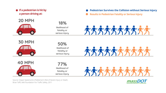
Source: Adapted from FHWA Achieving Multimodal Networks (2016) and Tefft, B.C (2011). Impact Speed and a Pedestrian’s Risk of Severe Injury or Death. Washington, D.C.: AAA Foundation for Traffic Safety
Speed management measures can improve safety and comfort for people biking by:
- Reducing motor vehicle speeds, reducing motor vehicle stopping distance, and the probability of bicycle/motor vehicle conflicts
- Providing an opportunity to consider installation of bicycle lanes
- Increasing the awareness of bicyclists
- Reducing the severity of motor vehicle/bicycle collisions
- Reducing intersection size and the probability of motor vehicle/bicycle conflicts.
Speed management measures can improve safety for motorists by:
- Reducing motor vehicle speed, thus reducing the probability and severity of crashes
- Reducing the frequency of vehicle overtaking on urban and neighborhood streets
- Providing design features (for example, roundabouts) that self-enforce lower vehicular speeds
- Providing motor vehicle drivers with multiple reminders of safe and appropriate operating speed
There are several tradeoffs to consider when developing a speed management or traffic diversion design. Many of these tradeoffs can be accounted for in the design process, such as:
- Speed management measures do not improve safety for motorists who fail to heed the indications of reduced design speed and operate a vehicle at speeds in excess of a road’s design speed. Advance signage can help to inform drivers of changes in proper operating speed when approaching speed management areas.
- Speed management and traffic diversion measures can slow emergency response since they often require slower operating speeds or diversions. It is important to coordinate speed management plans with local emergency response departments so that these impacts are minimized.
- Inappropriately designed or placed speed management and traffic diversion measures can impede transit vehicles. It is important to coordinate speed management plans with local transit agencies to avoid these impacts.
- Inappropriately designed or placed speed management and traffic diversion measures can impede large truck traffic. It is important to understand regional and local truck routes when developing speed management programs to avoid these impacts.
- Some speed management measures (particularly those involving horizontal and vertical deflection) can result in increased noise and headlight impacts to adjacent properties. Speed management design needs to be sensitive to these potential impacts.
- Inappropriately designed or placed speed management measures may impede maintenance operations (such as snow and ice removal, and street sweeping). Maintenance operations must be considered during the design process.
16.3 Applicability of Measures
Speed management measures are sometimes (but not exclusively) deployed in response to community concerns about high motor vehicle operating speeds and volumes. As a result, speed management measures are more often applied in developed settings such as urban areas, suburban town centers and villages, suburban high-density areas, and rural villages. Typical characteristics of settings associated with speed management are:
- Concentrated generators of pedestrian activity; for example, school campuses, elderly housing, downtown retail districts, “Main Street” shopping areas, public assembly venues (stadiums, auditoriums), recreation destinations (parks, playgrounds), health care complexes, and large employers
- Presence of people walking, either constant or in surges, along and across the street
- Neighborhood streets where the street serves both as a transportation facility and a community space
- Sensitive land uses (historical, tourist, retail, civic, institutional) abutting the street
- Transition zones, from higher to lower speed, e.g., when approaching a rural village
Speed management is most often applied to existing streets where vehicle operating speeds are in conflict with pedestrian activity and other aspects of the setting as described above. Some speed management measures (such as crossing islands and curb extensions) used as retrofit measures on existing streets should also be used as regular design elements on new or rebuilt streets where the presence of people walking and biking would be expected.
The needs of the setting must be balanced with the regional mobility function of the roadway when considering speed management measures, similar to many other aspects of roadway design. Speed management measures discussed in this chapter are most appropriate for local roads and minor collectors. Additional measures suitable for local streets (but too restrictive for other types of streets) are not discussed in this chapter, but may be found in the references listed at the end of the chapter.
In some circumstances, such as in a town center environment, where both high vehicular volumes and high presence of people walking and biking are present, speed management measures can be suitable for use on arterials. In some cases, these elements, such as crossing islands and curb extensions, should be considered as elements of good design for new roadways. However, intensive speed management programs are usually not applied to suburban and rural arterials since they primarily provide for regional travel and the settings for which speed management is desired are not usually found along arterials.
Speed management measures are not appropriate for freeways and expressways. The settings associated with speed management are not present along freeways and expressways. Table 16‑1 summarizes the applicability of various speed management measures to various roadway types under typical conditions. In Table 16-1 and Table 16-2, a one indicates common use in these settings, a two indicates that this treatment may be suitable in this setting, and a three indicates that the applicability depends on the specific context of the roadway in question. The specific measures are described in more detail in the following sections.
Table 16‑1: Speed Management Treatment Applicability by Functional Classification
| Treatment Type | Treatment | Local | Minor Collectors | Major Collectors | Minor Arterial | Major Arterial |
|---|---|---|---|---|---|---|
| Vertical Deflection | Speed Humps | 1 | 2 | 2 | NA | NA |
| Vertical Deflection | Raised Crosswalks | 1 | 1 | 2 | 3 | 3 |
| Vertical Deflection | Raised Intersections | 1 | 1 | 2 | 3 | 3 |
| Horizontal Deflection | Chicanes and Lane Offsets | 1 | 1 | NA | NA | NA |
| Horizontal Deflection | Curb Extensions | 1 | 1 | 1 | 1 | 1 |
| Horizontal Deflection | Medians and Pedestrian Refuge Islands | 1 | 1 | 1 | 1 | 1 |
| Horizontal Deflection | Spot Narrowing of Pavement | 1 | 1 | 1 | 2 | 2 |
| Horizontal Deflection | Neighborhood Traffic Circles | 1 | 2 | NA | NA | NA |
| Horizontal Deflection | Mini Roundabouts | 1 | 1 | 2 | NA | NA |
| Horizontal Deflection | Mid-Block Deflection | 1 | 1 | 2 | NA | NA |
| Physical Narrowing Treatments | Travel Lane Width Narrowing | 1 | 1 | 2 | 3 | 3 |
| Physical Narrowing Treatments | Road Diets/ Lane Removal | 1 | 1 | 2 | 2 | 2 |
| Physical Narrowing Treatments | Auxiliary Lanes | 1 | 1 | 1 | 1 | 1 |
| Measures to Narrow the Apparent Width | Curbside Parking | 1 | 1 | 1 | 1 | 1 |
| Measures to Narrow the Apparent Width | Street Furniture | 1 | 1 | 1 | 1 | 1 |
| Measures to Narrow the Apparent Width | Street Lighting | 1 | 1 | 1 | 1 | 1 |
| Measures to Narrow the Apparent Width | Street Trees | 1 | 1 | 1 | 1 | 1 |
| Measures to Narrow the Apparent Width | Raised Curbs | 1 | 1 | 1 | 1 | 1 |
| Measures to Narrow the Apparent Width | Gateways | 1 | 1 | 1 | 1 | 1 |
| Measures to Narrow the Apparent Width | Textured Pavement | 1 | 1 | 1 | 1 | 1 |
| Signage | Speed transition zones, advisory, and feedback signage | 1 | 1 | 1 | 1 | 1 |
Legend:
- 1: Often used for new design or retrofit programs in speed management settings
- 2: May be suitable
- 3: Applicability dependent on context or setting (i.e., high pedestrian activity, etc.)
- NA: Typically not applicable
Source: MassDOT
Table 16-2: Speed Management Treatment Applicability by Target Speed
| Treatment Type | Treatment | 20 MPH | 25 MPH | 30 MPH | 35 MPH and higher |
|---|---|---|---|---|---|
| Vertical Deflection | Speed Humps | 1 | 1 | 2 | NA |
| Vertical Deflection | Raised Crosswalks | 1 | 1 | 2 | 3 |
| Vertical Deflection | Raised Intersections | 1 | 1 | 2 | 3 |
| Horizontal Deflection | Chicanes and Lane Offsets | 1 | 1 | 1 | NA |
| Horizontal Deflection | Curb Extensions | 1 | 1 | 1 | 1 |
| Horizontal Deflection | Medians and Pedestrian Refuge Islands | 1 | 1 | 1 | 1 |
| Horizontal Deflection | Spot Narrowing of Pavement | 1 | 1 | 1 | 2 |
| Horizontal Deflection | Neighborhood Traffic Circles | 1 | 1 | 2 | NA |
| Horizontal Deflection | Mini Roundabouts | 1 | 1 | 2 | NA |
| Horizontal Deflection | Mid-Block Deflection | 1 | 1 | 2 | NA |
| Physical Narrowing Treatments | Travel Lane Width Narrowing | 1 | 1 | 1 | 3 |
| Physical Narrowing Treatments | Road Diets/ Lane Removal | 1 | 1 | 1 | 2 |
| Physical Narrowing Treatments | Auxiliary Lanes | 1 | 1 | 1 | 1 |
| Measures to Narrow the Apparent Width | Curbside Parking | 1 | 1 | 1 | 1 |
| Measures to Narrow the Apparent Width | Street Furniture | 1 | 1 | 1 | 1 |
| Measures to Narrow the Apparent Width | Street Lighting | 1 | 1 | 1 | 1 |
| Measures to Narrow the Apparent Width | Street Trees | 1 | 1 | 1 | 1 |
| Measures to Narrow the Apparent Width | Raised Curbs | 1 | 1 | 1 | 1 |
| Measures to Narrow the Apparent Width | Gateways | 1 | 1 | 1 | 2 |
| Measures to Narrow the Apparent Width | Textured Pavement | 1 | 1 | 1 | 1 |
| Signage | Speed transition zones, advisory, and feedback signage | 1 | 1 | 1 | 1 |
Legend:
- 1: Often used for new design or retrofit programs in speed management settings
- 2: May be suitable
- 3: Applicability dependent on context or setting (i.e., high pedestrian activity, etc.)
- NA: Typically not applicable
Source: MassDOT
16.4 Spacing and Frequency of Measures
Speed management measures include:
- Continuous measures along a corridor that alter the street cross section (for example, on-street parking or continuous planning of street trees)
- “Spot” measures applicable to only a small segment of street (for example, speed humps)
Continuous speed management measures are appropriate for extended lengths. Drivers are more likely to regard such features as an inherent characteristic of the street and not as measures “aimed” at their driving practices.
“Spot” speed management measures should be spaced so that the target speed is consistently maintained along the roadway segment. For example, vertical deflection countermeasures can be effective for achieving 20 mph speeds at 150-250 spacing. Measures placed too far apart for the target speed allow drivers to accelerate between measures, reducing their effectiveness in controlling speeds along the corridor. Measures placed too frequently for the target speed can become annoying for drivers and may lead to rapid acceleration and deceleration behavior. The designer should also consider placing “spot” treatments placed at or near specific points of conflict – such as locating a raised crosswalk at an existing pedestrian crossing.
A comprehensive speed management plan should consider the network effects of deploying speed management across a zone to discourage diversion to parallel streets.
16.5 Vertical Deflection Countermeasures
Speed management measures may include alterations to the profile of the street (humps and elevated segments of streets).
Speed Humps and Cushions
Speed humps and cushions are intended to let vehicles operating at intended speeds pass with little discomfort to the driver, no bouncing of loads in trucks, and little noticeable stress (for example, bottoming out) of the vehicles. Because driver discomfort at humps and cushions rises rapidly as their design speed is exceeded, these vertical deflection measures are an effective measure for controlling speeds.
Speed humps and cushions can be appropriate for minor collectors and local roads. On higher-classified streets (major collectors or arterials), the design speed of 15-20 miles per hour is likely to be inappropriate and inconsistent with the function of such streets.
Vertical deflection measures may generate noise from vehicles braking and accelerating. Noise impacts on nearby residents can be mitigated through careful locating of the speed humps and cushions, or by spacing them closely to encourage constant speeds. The maximum recommended spacing between speed humps or cushions is 500 feet.
Speed Humps
Speed humps are typically 12-14 feet in length and rise to a height of 3 inches. A common profile, the parabolic crown, illustrated in Figure 16‑2, permits comfortable crossing at design speed, but makes crossings increasingly uncomfortable as design speed is exceeded.
Figure 16‑2: Parabolic Speed Hump Profile
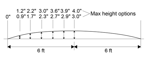
Source: MassDOT
Speed humps may be constructed from a wide variety of materials: asphalt, textured or colored asphalt, and poured and stamped concrete. Typically, the space between the end of the hump and the curb is left open, allowing the gutter drainage to continue functioning unhampered.
Speed Cushions
The speed cushion is a variety of speed hump that has gaps between raised areas to enable a vehicle with a wide track (e.g., a large emergency vehicle, trucks, or buses) to pass through the treatment without vertical deflection. Speed cushions provide much of the speed management impact of a speed hump while also allowing bicycle lanes and storm drainage to continue unhindered at the original street grade.
Raised Crosswalks
Raised crosswalks, shown in profile in Figure 16-3, are frequently used to complement pedestrian crossings, particularly where curb extensions are in place. Raised crosswalks make a pedestrian more prominent in the driver’s field of vision, thereby improving the safety of people crossing the road. Raised crosswalks also serve to protect the pedestrian crossing from intrusion by on-street parking. Ramp lengths from the roadway level to the pedestrian crossing level are typically 6 feet (minimum 3 feet), and the typical length of the level crossing is 10 feet, giving a total typical length of 22 feet. A simple straight ramp is typically used, and its length may be adjusted based on the existing roadway grade and desired ramp slope. The level crossing width may be adjusted based on the need for a wider level crossing at locations with high pedestrian volumes.
Figure 16‑3: Raised Crosswalk Profile
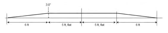
Source: MassDOT
Raised Intersections
The concept of the raised crosswalk can be extended to an entire intersection, raising the entire intersection to sidewalk height. The raised intersection provides benefits to crosswalks on all legs of the intersection. Raised intersections employ many of the same design elements as raised crosswalks; however, the designer needs to pay special consideration to drainage issues and the demarcation of intersection corners through pavement changes, markings, or bollards.
16.6 Horizontal Countermeasures
Deflecting the vehicle from an otherwise straight path is an important speed management action that reduces vehicle speed. The relationship of sight distance and curvature to operating speed is a basic relationship for road design at all speeds as described in Chapter 3. For the lowest design speeds associated with speed management (5-15 miles per hour), it is necessary to extend the ranges of stopping sight distance and minimum radius, by extrapolating the AASHTO values adopted for higher speeds, illustrated in Figure 16-4. Stopping sight distances of 30 feet and 50 feet are extrapolated for lower speeds of approximately 5 mph and 10 mph, respectively. Minimum radii of 10 feet and 25 feet are extrapolated for lower speeds of approximately 5 mph and 10 mph, respectively.
Figure 16‑4: Low-speed Design Parameter
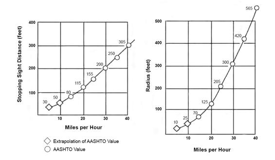
Source: MassDOT
Chicanes and Lane Offsets
The simplest measure for deflecting traffic is the narrowing of one side of the street by an amount that requires the through traffic to deflect from its previously straight path, as shown in Figure 16‑5. A series of such deflections, typically called chicanes, multiplies in effectiveness as it extends throughout the entire length of the block. Chicanes can be combined with center median islands to prevent drivers from cutting a straight path across the center line.
Figure 16-5: Mid-block Deflection (Chicane)
Source: MassDOT
Traffic lanes can be offset at an intersection to reduce speed through the intersection, or mid-block, as shown in Figure 16‑6. On streets with parking on one side, the offset results from alternating the side of the street containing the parking. At “T” intersections with a left-turn bay provided, the left-turn lane requires an offset for through traffic in at least one direction of travel. On streets with diagonal parking on one side and parallel on the other, the offset at the intersection results from alternating the sides on which each type of parking is provided.
Figure 16-6: Lane Offsets from Parking
Source: MassDOT
Curb Extensions
Narrowing the street at an intersection, through the use of curb extensions, is a versatile and widely used speed management measure, as shown in Figure 16‑7.
Figure 16-7: Intersection Curb Extensions
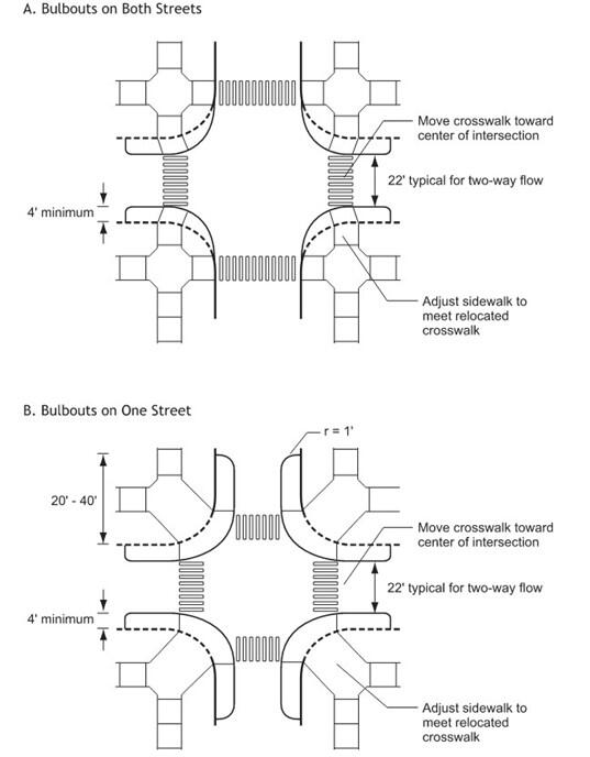
Source: MassDOT
In addition to slowing traffic due to reduced pavement widths, curb extensions delineate on-street parking, shield the ends of the parking lane from moving traffic, and discourage drivers from using an empty parking lane for overtaking other vehicles. They also prevent illegal parking at corners, thereby improving sight lines for all users.
Curb extensions reduce the pedestrian crossing distance while increasing the pedestrian space on the intersection’s corners. Curb extensions can also benefit vehicular traffic, by moving the stop bar on the approach lanes further into the intersection, thereby reducing the intersection size and signal clearance intervals at signalized intersections. The reduced intersection size can, in some instances, solve sight-distance deficiencies on the intersection approaches. Curb extensions can prevent parking close to intersections, and thus improve sight distance from cross streets. Also, curb extensions frequently reduce the “wasted” pavement at intersections (i.e., areas of pavement unusable by either vehicles or pedestrians near the corners). Fire hydrants are often located near intersections so that curb extensions result in no loss of legal parking.
Curb extensions can be used on one or both of the intersecting streets, or on any combination of approaches. The width of the roadway at the curb extension is typically no wider than necessary to accommodate the through lanes, providing 10 to 12 feet per lane plus additional offset of 1 to 2 feet from the edge of the traveled way. Curb extensions should only be used in conjunction with on-street parking so that they do not pose an unexpected hazard to bicyclists and motor vehicles. The selection of design vehicles and their corresponding turning radii should guide curb extension design. Information on selecting design vehicles and more details on intersection design criteria are presented in Chapter 6.
With curb extensions, the increase in sidewalk area provides space for street furniture such as fire hydrants, information kiosks, benches and plantings. The additional sidewalk space is particularly useful where local regulations require buildings to be located adjacent to the sidewalk, thereby putting a premium on sidewalk space.
Typically, curb extensions are cost effective, since a single intersection treatment affects traffic in all directions on both intersecting streets. Because of their high visibility, curb extensions can be an important entrance feature for a neighborhood or a district of special interest.
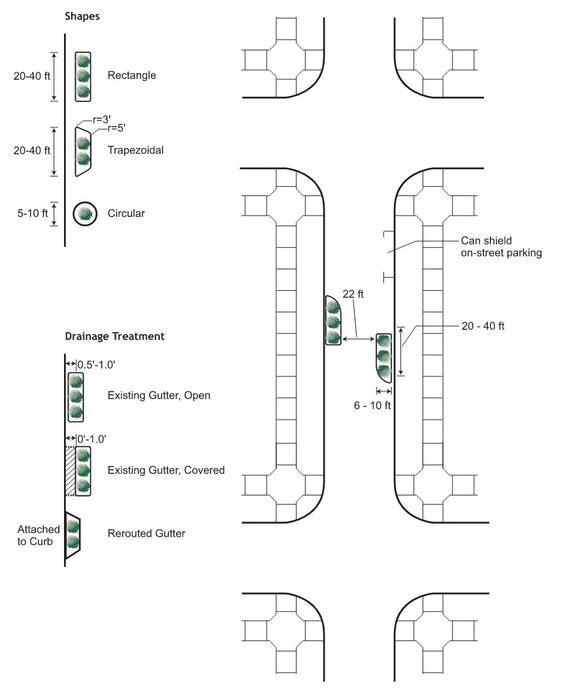
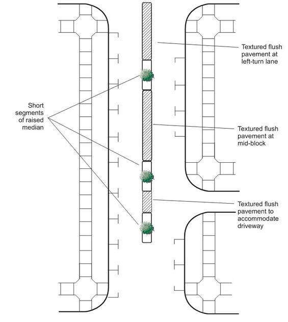
Medians and Pedestrian Refuge Islands
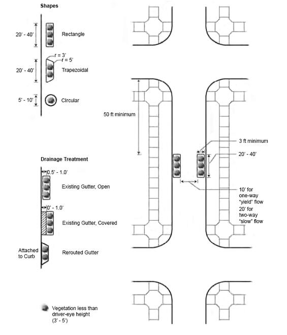
Traversable medians, typically built of textured or contrasting materials such as stamped concrete, bricks, pavers, or cobblestones can be effective speed management devices particularly where periodic segments of raised median are included, as shown in Figure 16‑8. These medians are flush with the travel lanes but are notably different, both in appearance and in feel to the driver. Traversable medians narrow the real and apparent width of the street, and provide deflection at end points, while still permitting unlimited driveway access across them. They can serve as left-turn lanes and allow for passing of double-parked cars. Further, traversable medians offer opportunities for emergency vehicles to bypass stopped traffic. At intersections, the ends of the traversable medians can extend all the way through the crosswalk, thereby providing some pedestrian refuge.
Pedestrian refuge islands are short divisional islands located at crosswalks. Pedestrian refuge islands are a FHWA proven safety countermeasure. Pedestrian refuge islands may be located at intersections or midblock locations. These islands allow pedestrians and bicyclists to cross only one traffic stream at a time and provide some degree of protection from vehicular traffic while waiting for a gap to finish their crossing.
These islands should include raised curbs with a cut-through at the pavement level for wheelchair users. The cut-through shall be at least 5 feet wide or as wide as the crosswalk, whichever is greater. Pavement-level cut-throughs shall have detectable warning surfaces extending the full width of the opening and be graded to drain quickly. The pedestrian refuge island should be at least 6 feet wide from the face of the curb to the face of the curb; however, narrower widths may be acceptable in constrained locations. The island should not be less than 12 feet long or the width of the crosswalk, whichever is greater. The selection of design vehicles and their corresponding turning radii should guide pedestrian refuge island design. Refer to Chapter 6 for further guidance on channelization islands, islands that serve as mid-block path crossings, and for information on selecting design vehicles.
Raised mid-block islands should be short in length, typically less than 70-90 feet. Longer islands are likely to cut off access to too many properties and do not add to the deflection. Ideally, these short segments of median are sited to avoid blocking property access, although confining the occasional driveway to right-in/right-out access may be reasonable. The minimum island size should be 50 square feet. Larger islands can sometimes support plantings if adequate soil volumes and irrigation are provided. See Chapter 13 for additional planting guidance.
All raised islands should also include an approach nose, offset from the edge of the traffic lane and appropriately treated to provide motorists with sufficient warning of the island's presence. This can be achieved in various ways, such as illumination, reflectorization, marking, signage, and/or by the size of the island.
Figure 16-8: Median Islands
Source: MassDOT
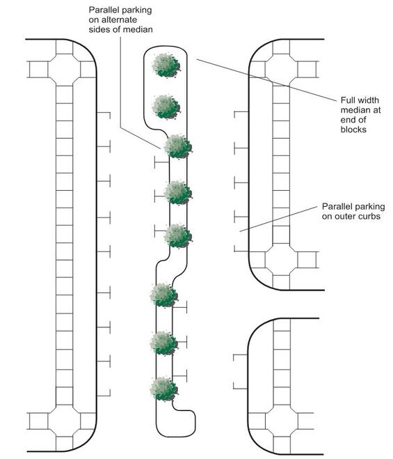
Horizontal deflection can be achieved with median islands where there is on street parking by eliminating parking near the island. Curb lines can also be adjusted to accommodate the crossing islands. On divided streets, parking can be added along the median. Where the total street width permits only one lane of parking along the median, that parking lane can be alternated, as shown in Figure 16‑9. With this approach a planted median can give the appearance of a double row of trees, although only a single row is present at any point along the street. The designer should refer to Chapter 13 for additional guidance on tree planting in the medians.
Figure 16-9: Parking on Median Islands
Source: MassDOT
Spot Narrowing of Pavement
Narrowing a street at mid-block locations, as illustrated in Figure 16‑10, can capture much of the benefit of a far more extensive narrowing. Narrowing the street at mid-block locations serves to reduce the speed of vehicles not only at the narrowing itself, but also for the adjacent street segments, where motorists decelerate and return to normal running speed.
Figure 16-10: Mid-block Street Narrowing
Source: MassDOT
Mini Roundabouts and Neighborhood Traffic Circles
Raised circular islands constructed in the center of residential street intersections, mini roundabouts and neighborhood traffic circles can reduce speed by requiring drivers to maneuver around them. Sometimes used instead of stop signs, they are unsignalized measures that can support low vehicle speeds and enhance safety for all users.
Mini roundabouts have traversable islands and yield control on all approaches, so they function like other roundabouts. Neighborhood traffic circles are typically built at the intersections of local streets to provide speed management or aesthetic benefits. They operate as two-way or all-way stop-controlled intersections, typically without raised channelization to guide approaching traffic into the circulatory roadway.
Two characteristic features of roundabouts—splitter islands on approaches and the central circle—provide a significant reduction in vehicle speeds and corresponding increases in driver attentiveness. The deflection provided by the splitter islands encourages a decrease in speed as drivers approach the intersection. Within the roundabout, the radius of the central island reinforces the low operating speed. At some roundabouts landscaping or man-made features within the central island terminate the view on approaching roadways, thereby contributing to reduction of the operating speed of approaching traffic. Guidelines for the placement and design of roundabouts are provided in Chapter 6 and in the MassDOT Guidelines for the Planning and Design of Roundabouts.
Because of its circular central island, the neighborhood traffic circle is frequently confused with a roundabout. However, the neighborhood traffic circle differs from a roundabout in important ways. Neighborhood traffic circles are typically smaller than roundabouts and do not merge traffic into a stream around a circulating roadway. Unlike the roundabout, the neighborhood traffic circle is not a traffic control device. Rather, at the neighborhood traffic circle, right-of-way is assigned by stop control (often all-way stop control). Neighborhood traffic circles usually do not have splitter islands on their approaches, although these are sometimes provided to absorb excess pavement width on approaches or to provide pedestrian refuge. For automobiles, operations at a neighborhood traffic circle are similar to those at a roundabout, with vehicles proceeding around in a counterclockwise direction. Large trucks (single unit (SU) trucks or larger) make right turns and through movements by entering the circle and proceeding counterclockwise. However, they make left turns by turning in front of the mini-traffic circle, after yielding right-of-way.
This pattern of movement can be hazardous where truck and buses are present on a regular basis. Neighborhood traffic circles can also pose significant challenges for emergency vehicles. As a result, neighborhood traffic circles are not recommended for most locations. Roundabouts and mini-roundabouts should usually be considered in lieu of neighborhood traffic circles.
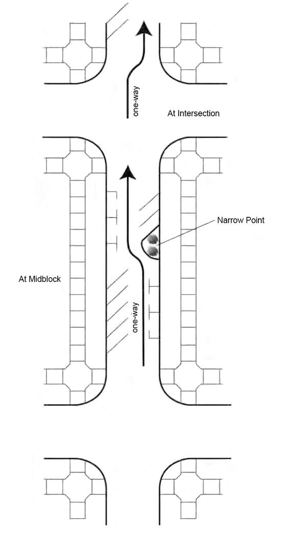
Mid-Block Deflection Treatment
Mid-block deflection treatments are a speed management measure that reduces vehicle speed by introducing deflection in the vehicle path around a raised island. These can be used as standalone treatments or used in series to manage vehicle speeds along a corridor. Unlike a mini roundabout or neighborhood traffic circle, this mid-block deflection treatment has no traffic control function and only provides a physical geometric treatment for vehicles to navigate. The island of a mid-block deflection treatment should be oblong to provide sufficient deflection in a vehicle’s travel path while continuing to support navigation by fire trucks and other design vehicles. While similar to a median island, a mid-block traffic calming deflection treatment typically entails widening the outside edge of the roadway to accommodate the curved, deflected path alignment. The principle of the fastest path check for a roundabout can be adapted to evaluate the ability of a design vehicle to navigate around a mid-block deflection treatment and the effectiveness of the speed management function.
A mid-block deflection treatment can discourage acceleration along a straight, visible stretch of roadway by deliberately terminating the view down the street with landscaping within the island area. Beyond its speed management value, the highly visible island of the mid-block deflection treatment can serve as a major demarcation point at a neighborhood boundary or as a setting for a monument or other display.
16.7 Physical Narrowing Countermeasures
Travel Lane Width
Reducing travel lane widths can reduce vehicle speeds, reduce pedestrian crosswalk distances, and maximize the space available for bicycle lanes and sidewalks.
Where speed management is intended, driving lane widths should be 10 feet, a width widely accepted as appropriate for residential and minor collector streets. A larger lane width (11 feet) is appropriate for outer (curb) lanes on streets where on-street parking is not present and on arterials or other roadways that carry large numbers of trucks and buses.
Road Diets/Lane Removal
The pavement width of the street can be allocated in a manner that gives more space to pedestrians, bicycles, and parking, by reducing the width of the motor vehicle traveled way. This re-allocation is referred to as “road diets” or “roadway reconfiguration” when applied to existing streets. By narrowing a street’s pavement width and/or travel lanes, road diets can also serve as a tool for speed management in addition to improving conditions for pedestrian and bicycle users. For roadways with average daily traffic of 25,000 of less, the elimination of a travel lane on a four-lane roadway and conversion of another lane to a median with turning pockets is a Proven safety countermeasures for all users without adversely affecting roadway capacity.
Transparent decision-making, community conversations, and operational analyses can help to evaluate the inevitable tradeoffs resulting from road diets. For more guidance on cross section decision-making, refer to NCHRP Report 1036: Roadway Cross-Section Reallocation: A Guide.
Auxiliary Lanes
Auxiliary (left turn and right turn) lanes should be used sparingly with speed management. Typically, rear-end collisions between a left-turning vehicle and a following vehicle are less frequent and less severe in low speed settings than in higher speed settings. Further, the occasional blockage of through traffic by a left-turning vehicle should not be considered a detriment in a low speed setting. Occasional and irregularly timed variations in traffic flow are an intended consequence of speed management.
When on-street parking is present, as shown in Figure 16‑11, left-turn lanes can generally be accommodated (when necessary) within the existing pavement width on the intersection approach leg by removing parking spaces on both sides of the street at the intersection. On streets without parking, the existing pavement width may not be adequate to accommodate a left-turn lane, and the approach may therefore have to be flared to accommodate the left turn lanes. Auxiliary lanes (typically left-turn lanes) should typically be 10 feet wide in areas where speed management measures are employed.
Right-turn lanes are inadvisable in most speed management settings. Their emphasis on vehicular accommodation, the additional crossing distance they create for pedestrians, and the increased possibility of vehicle conflicts with pedestrians are all likely to negate the speed management goals for the street.
Figure 16-11: Left-turn Lanes, Speed Management Values
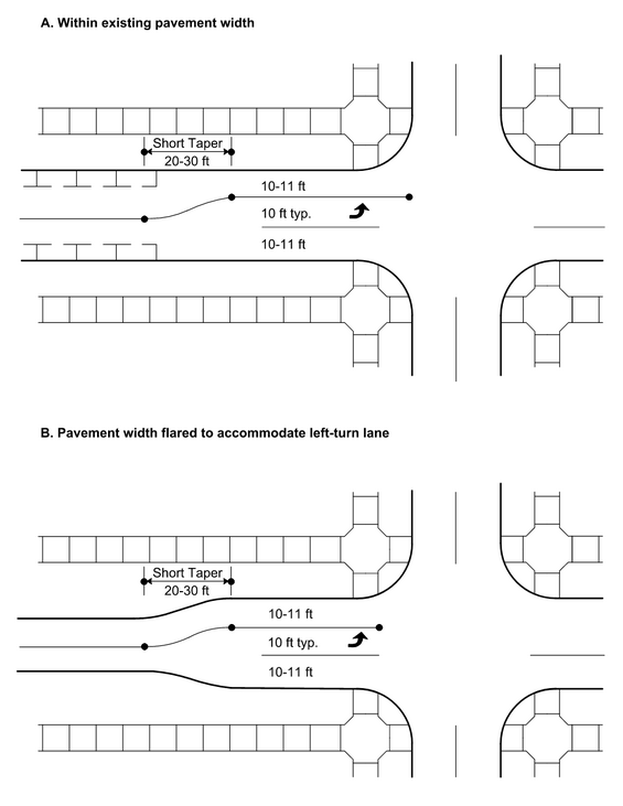
Source: MassDOT
16.8 Measures to Narrow the Apparent Width
Reducing the apparent street width and creating a sense of enclosure can help to manage speeds. Enclosure is the sense that the roadway is contained in an “outside room” rather than in a limitless expanse of space. Drivers’ sense of speed is enhanced by providing a frame of reference in this space. The same sense of enclosure that provides a comfortable pedestrian experience also helps drivers remain aware of their travel speed.
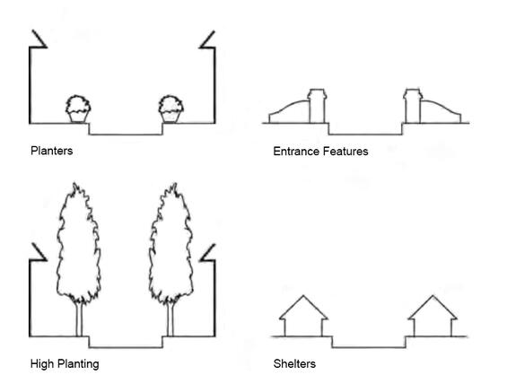
Elements that influence the apparent width of a street and help to keep drivers aware of how fast they are traveling are illustrated in Figure 16‑12, listed below, and discussed in the subsequent sections.
- Building placement along the street
- The presence or placement of trees and curbside parking along the street
- Street furniture including lights, benches, and other elements
- Edge treatment of the pavement
The placement of buildings directly along the street (i.e., with shallow or no setbacks from the right-of-way) is a highly effective speed management measure, but not part of MassDOT projects. Building sites are, by definition, outside the public right-of-way. Their regulation is usually the prerogative of local government jurisdictions (city or town). Effective complements to speed management design include:
- Regulatory changes, by local governments, to encourage building placement adjacent to streets, particularly in commercial areas.
- Urban design practices that enhance urban or rural village characteristics, such as detailing the building facades, placing signs and symbols on the buildings, and making pedestrian access easy and prominent.
Figure 16-12: Elements of Apparent Street Width
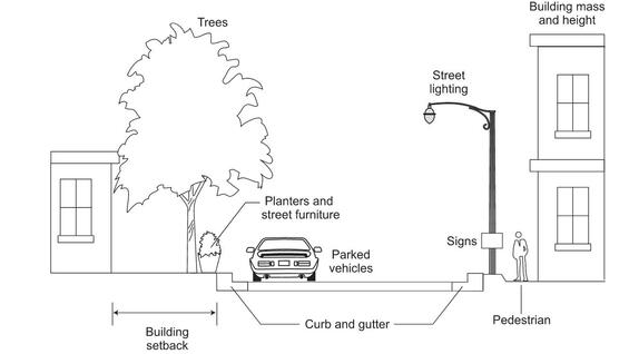
Source: MassDOT
The following sections describe elements that can be part of roadway projects to narrow the apparent street width. An additional tool for narrowing the apparent width is the use of gateways, which are also described later in this section.
Curbside Parking
The sense of enclosure resulting from parked cars, the articulated appearance of parked cars, the entry/exit vehicular maneuvers, and the pedestrian traffic generated by occupants of parking/departing vehicles, all contribute to speed management on streets with parking. Curbside parking of all types should be considered in the context of bicycle use of the street since parking maneuvers and door openings are a safety hazard to bicyclists.
The dimensions for on-street parking, in contrast to those for moving vehicles, are not intended to change behavior, but rather are intended to make parking safe and efficient. Although spaces do not need to be striped, the typical dimensions for on-street parallel spaces are a width of 8 feet, although in constraint locations the width may be reduced to 7 feet, and a length of 20-22 feet. In many locations, particularly with short sections of curb face interrupted by driveways or hydrants, the length of parking spaces can be increased without reducing the number of spaces. The selected width should also take into consideration whether bicycle lanes are present and the volume and composition of traffic on the street.
The parallel parking maneuver can be expedited and made more convenient to drivers by marking a “box” at one or both ends of the parking space, as illustrated in Figure 16‑13. If parking is allowed, this treatment is particularly suited to roadways with higher traffic volumes. The box striping plan can help minimize the delays caused by the parking maneuver. With these boxes in place, the entering or exiting motorist has available the marked dimensions of the space (typically 22 feet, although smaller spaces are possible with this treatment) and also the length of both of the attached boxes (a total of 8-10 feet) to enter and exit the parking space.
Diagonal parking is not commonly used because of limitations in roadway width and potential conflicts with people biking on the street, but can be an element of speed management in areas with a high demand for parking and sufficient pavement width. The allocation of pavement (parking versus travel lanes) and the “friction” of parking maneuvers contribute to speed management. Diagonal parking may be more appropriate if a bicycle lane is not located behind the parking stalls, as limited visibility increases the risk of collisions with people biking. However, careful consideration should be given to the trade-offs due to conflicts of motor vehicles with people walking and biking along the street.
Figure 16-13: Curbside Parking
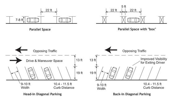
Source: Adapted from Back-In Angle Parking in the Central Business District, John A. Nawn, 2003
“Back-in” diagonal parking, shown in Figure 16‑13, is another approach to angle parking. Parking dimensions are the same as head-in diagonal parking. However, the back-in layout permits exiting drivers to have a clear view of on-coming traffic, bicyclists, and pedestrians in the street as they exit the space. Visibility leaving the space is superior to head-in parking, where exiting drivers are likely to have their view of on-coming traffic obscured by the adjacent vehicle. An additional advantage of back-in parking is that the open doors of the parked vehicles block passenger access to the street, and instead channel passengers toward the sidewalk, a safety benefit for all users and particularly for children. Finally, back-in parking places the cargo area (trunk, hatchback, truck bed) for almost all vehicles on the curb, and not in the street adjacent to traffic lanes.
The principal drawbacks of back-in parking, when compared with head-in parking, are the need for a motorist to stop in the travel lane before backing into a space and increased potential for vehicle overhang on sidewalks. The overhang is a significant concern if the sidewalks are narrow. The provision of wheel stops can help address the overhang issues, although the rear-wheel overhang dimension varies widely across the motor vehicle fleet. Wheel stops can also pose a challenge for maintenance operations such as street sweeping and snow plowing.
Street Furniture
Street furniture elements include signs, signals, street lights, walls, fencing, and pedestrian furnishings such as benches, shelters and trash receptacles. In urban and rural village settings, it is desirable for street furniture to border the street and provide a separation between the pedestrian pathway and traffic. Poles and planters are normally located 2-3 feet from the back of curb, leaving room for the opening of car doors or for movement of pedestrians to/from parked automobiles, as shown in Figure 16‑14. Benches, kiosks and shelters should allow sufficient space (6-8 feet from curb) for the comfort of their users.
Figure 16-14: Desirable Street Furniture Setbacks
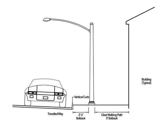
Source: MassDOT
Street Lighting
While the primary purpose of street lighting is to enhance nighttime visibility for safety, street lighting can also support speed management. Street lighting can affect the apparent width of the roadway in several ways:
- By the size and placement of the street lights
- By the height and pattern of light when illuminated
- Through the sense of enclosure created by overhead street lights
Pedestrian-scale lighting, which typically has a luminaire mounting height of 20 feet of less, can support a lower-speed environment by signaling a context where pedestrians are present. Where street trees are present, the lamp height should be beneath the tree canopy, or between trees.
Pole spacing depends on the mounting height. Lower-mounted lamps typically require closer spacing, since the area illuminated by each lamp is smaller. Pedestrian-scale lighting may need to be combined with roadway-scale lighting (which has a luminaire mounting height of 20 feet or higher) to achieve adequate illumination levels across the roadway. Lighting fixtures should be appropriately shielded to minimize undesirable light pollution and the color emitted (white light is often preferred in developed areas) should be consistent with the setting.
In addition to possible speed management influences, street lights are an important feature of the urban design for a district. In many cases, municipal or district standards apply to the selection and placement of street light fixtures.
For additional guidance, refer the FHWA’s 2022 Pedestrian Lighting Primer.
Street Trees
Tree trunks lining the roadside create a sense of enclosure and contribute to a reduced apparent width. The overhead tree canopy further adds to the perception of a narrowed road since the light/shade patterns on the pavement created by the trees contribute to a sense of texture on the pavement. Guidance for the planting of street trees is provided in Chapter 13.
Raised Curbs
Curbs are important in traffic calmed settings because they signal a lower-speed context to motorists. Curbing is not normally paired with clear zones typical of rural areas and high speed environments. Further, a raised curb permits a placement of roadside objects (trees and street furniture) close enough to the travel lanes to have a pronounced speed management effect.
Short segments of streets with no curb within longer segments of curbed streets can also be a speed management measure. In such instances, the edge of the traveled way is delineated by pavement markings, change in pavement texture, or paving bands of a contrasting color and texture. The edge of the traveled way can be further delineated by bollards, planters or other street furniture. Curbless sections can also serve as “shared streets” which are designed to be fully part of the public realm and are integrated into the surrounding context. Examples of such shared streets are plazas in a town center, market places with street vending, streets regularly used for festivals, and places (e.g., in front of churches or city halls) of unusual civic interest.
Gateways
Signs, pavement markings, archways, roundabouts, street-side features, or any combination of the measures above that function as gates or portals, but do not restrict entry, can be an effective speed management device. Such gateway features appear to narrow the road and therefore signal a lower-speed context to approaching motorists. Gateways may be placed at transitions between contexts, for example, where an arterial roadway enters a rural village or suburban town center. Gateways can also be placed at the entrance dead-end street system or a special area, signaling to unfamiliar motorists that a street is not a likely cut-through route or requires increased attentiveness. In addition to their speed management function, gateway features can serve as transit waiting areas, information kiosks, and mountings for signs and lighting.
As shown in Figure 16-15, gateway features may be placed within the street right-of-way. Minimum clearance from the street is 2-feet from the back of curb. When placed near or at an intersection, gateway features should not obstruct the intersection sight triangle as described in Chapter 3.
Figure 16-15: Example Gateway Features
Source: MassDOT
Marking Measures: Textured Pavement
Visual cues and the texture of the roadway surface can play an important role in maintaining safe speeds and promoting traffic safety.
Textured pavement encourages motorists to be aware of an area of special concern due to the appearance of the texture, vibration, more noticeable motion of the vehicle and tire noise. Pavement texture alone, at isolated locations, is not an effective speed management measure. Rather, textured pavement is more appropriate in support of other speed management measures such as mid-block narrowing, intersection curb extensions, or roundabouts.
Flexible pavement materials (i.e., asphalt) can be colored or stamped with patterns, and are often the material of choice for speed humps and crosswalks. Rigid pavement (i.e., concrete and stamped concrete) is regularly used for flat-top humps, and for crosswalks. Rigid materials, such as concrete pavers, are frequently used for full intersection designs, raised intersections, crosswalks, and in connection with mid-block speed management measures such as narrowing and splitter islands. Paver-insets need to be constructed so that their long-term serviceability is ensured given the freeze-thaw cycles common in this region.
16.9 Speed Transition Zones
A transition zone is a series of measures placed over a distance to help drivers recognize that the roadway environment is changing—for example, from a rural to a suburban or urban area. This gives the driver enough time to reduce speed before entering the new zone. A transition zone may include advisory and feedback speed signage, curb extensions, raised crosswalks or intersections, raised medians, or landscaping to incrementally reduce vehicle speeds.
16.10 Inappropriate Treatments
Some treatments are inappropriate for use as part of a speed management program, as outlined below.
Traffic Diversion Measures
Traffic diversion measures are intended to reduce traffic on certain roadways and intentionally redirect traffic movements onto other roadways, but are unlikely to have a significant influence on operating speeds. However, traffic diversion measures can be part of a comprehensive plan to create lower-volume, lower-speed corridors that are comfortable for biking without dedicated or separated bicycle facilities.
Street Closure
Complete closure of a street, such as through gates, barricades, or pavement removal, may be appropriate as part of a larger planning effort (for example, pedestrianization of a street) but should not be considered as part of a speed management program. Street closure can lead to unintended consequences, including diverted traffic, increased vehicle miles traveled, and degraded emergency services, and therefore is not a remedy for neighborhood traffic problems.
Stop Control
Stop control, considered to be a speed management measure by many neighborhood groups, can be an appropriate traffic control decision under special circumstances. However, stop signs are traffic control devices that help to assign who has the operational right-of-way movement through an intersection and should not normally be considered a speed management tool. Warrants supporting the use of two-way and all-way stop are provided in the MUTCD. Some factors that may suggest use of all-way stop control include a lack of an obvious major and minor street, large volumes of turning movements, nearby pedestrian generators (park, school), and single through lanes in all directions.
Advocates of neighborhood speed management tend to overrate the effectiveness of stop control, and often request it at inappropriate locations. Excessive numbers of stops are difficult to enforce and can be a nuisance to even careful motorists. Over time, the misuse of stop control contributes to a reduction in motorist compliance.
Rumble Strips
The use of rumble strips as a speed management measure is inappropriate, since these are typically used as a warning device at high-hazard locations, such as isolated, high-volume, rural intersections. Further, rumble strips are hazardous to bicyclists, and the noise generated by them is likely to be problematical in neighborhoods. A further reason to avoid rumble strips as a speed management measure is that they do not compel a reduced speed as do other traffic control measures, and drivers eventually learn to ignore them.
16.11 Administering a Speed Management Program
Requests for speed management often come from neighborhood groups. Speed management programs should be planned in a design dialogue, conducted on-scene in the subject area, involving residents, property owners, business operators, emergency responders, and the roadway owner in intensive hands-on work sessions. A successful program of speed management measures requires skilled gathering and interpretation of input and applying a large measure of judgment in developing the measures.
Formal traffic survey techniques are often ineffective in forming speed management programs. Requiring petitions from residents, business or property owners as a prerequisite for installing speed management measures is inadvisable. Petitions voluntarily submitted by stakeholder groups can be one of a number of useable inputs to the design of any speed management program and can be a measure of the community’s perceived need for improvement and their willingness to fund it. However, such petitions should not be required. They are expensive, both in terms of funding and managerial attention required by the speed management program. Further, the petition process is often divisive, with the outcome likely to vary greatly depending on the wording of the petition and the outlook of the person collecting signatures.
Attempting to plan a program of speed management based on numerical scores or quotas is not advisable. Numerical scoring schemes will focus on those traffic characteristics that are easily measured (specifically, speeds, traffic volumes and collisions), thereby furnishing an incomplete and often misleading analysis of the need for speed management. Factors that are important to the community may not register in this type of numerical analysis. These important factors include the character of residential neighborhoods, historical value, type and value of retail business, neighborhood institutions and aesthetic character.
It is important to determine and discuss the benefits and impacts of various speed management measures with community members so that a well-founded speed management program can be prioritized and implemented. In some cases, gathering numerical data is expensive and time consuming, and can drain the speed management program of funds needed for producing the measures themselves. However, before-and-after studies and the use of low-cost, temporary measures (such as carefully arranged construction barrels) can be used to identify the effectiveness of existing or proposed speed management measures to build consensus around a speed management plan.
16.12 For Further information
- A Guide to Vertical Deflection Speed Reduction Techniques: Planning and Design of Speed Humps, Speed Tables and Other Related Measures (RP-038C-E). ITE, 2022.
- Achieving Multimodal Networks. FHWA, 2016.
- MassDOT Safe Speeds
- Pedestrian Lighting Primer. FHWA, 2022.
- Tefft, B.C., Impact Speed and a Pedestrian’s Risk of Severe Injury or Death, AAA Foundation for Traffic Safety, Washington, D.C., 2011
- Traffic Calming ePrimer. FHWA.
- Traffic Calming – State of the Practice. ITE/FHWA, 1999.
- Urban Street Design Guide. NACTO, 2013.