11.1 Introduction
This chapter describes the design considerations for shared use paths. Shared use paths—also called trails, multi-use paths, or bike paths—are off-road infrastructure that are physically separated from motorized vehicle traffic and designed for use by people of all ages and abilities. Types of shared use paths include:
- Rail trails, which are built on abandoned rail beds
- Rails with trails, which run adjacent to active rail lines
- Sidepaths, which run adjacent to roadways
- Other types including linear parks, canal towpaths, waterfront trails, and paths along utility corridors
Refer to the MassTrails Shared Use Path Planning Primer for examples of each path type.
Shared use paths are fully accessible and designed to accommodate a variety of users, including walkers, bicyclists, joggers, people with disabilities, skaters, and pets. These users can be on the facility for a variety of purposes including recreation, commuting, and local travel. A shared use path can accommodate various users in one or more treadways. A treadway is defined as a portion of the pathway designated for a particular user or set of users.
In the design of any type of path or trail, care should be taken to design elements that are compatible within the context of the project while providing a level of comfort that allows the path to be used by people of all ages and abilities. Shared use paths are designed for a variety of settings throughout the Commonwealth including agricultural or natural areas, rural towns, and suburban and urban neighborhoods. Path materials, barrier-types, landscaping, signage, walls, and fencing should be properly selected to complement the character of the area in which the path is built.
In contrast to shared use paths, greenways tend to be recreational facilities through backcountry or other remote areas. These facilities are generally unpaved trails and can serve hikers, mountain bikers, equestrians, or other off-road users. This chapter does not discuss greenways or other types of recreational off-road trails such as all-terrain vehicle trails, dirt bike trails, or snowmobile trails. MassDOT does not build greenways, as MassDOT facilities must be fully accessible. Similarly, this chapter does not discuss the design of sidewalks and on-road bicycle facilities. These design features are integrated into the roadway cross-section and are described in Chapter 5. The designer should refer to AASHTO’s 2004 Guide for the Planning, Design, and Operation of Pedestrian Facilities and 2012 Guide for the Development of Bicycle Facilities for more detailed design guidance for these facilities. The Manual on Uniform Traffic Control Devices (MUTCD) 2009 edition also provides information on signing and pavement markings for bicycle facilities.
11.2 Path Networks
Designers of shared use paths may choose from a variety of facility types to satisfy project goals and to serve users of all ages and abilities. Shared use path networks complement and may connect with on-road bike networks. Even when a shared use path or sidepath is provided, bicyclists can use the nearby or adjacent roadway if it is not limited access. Shared use paths are a complementary, non-motorized extension to the street network and should not preclude shared use of streets either by regulation or design. Designers should always consider the need for appropriate shoulder widths and on-road bicycle facilities to serve on-road bicyclists. Where pedestrian or bicycle use is prohibited or difficult to accommodate on a roadway, alternative access for pedestrians and bicyclists via convenient paths to all linkages and destinations served by the roadway is a possible solution. A well-planned and designed network of shared use paths and trails can achieve the following objectives:
- Provide shortcuts between generators of pedestrian and bicycle activity
- Provide pedestrian and bicycle access to areas served only by highways on which pedestrian and bicycle travel is prohibited or with a high level of traffic stress
- Provide pedestrian and bicycle access to areas not well-served by roads
- Provide a training ground or alternative experience for bicyclists who are not comfortable with on-road cycling
- Provide an integrated recreation facility that is in itself a destination for users and a valued community resource
Shared use paths can be of any length from short connections between streets to long corridors following features like rivers or railroad corridors. A path network should be integrated with other pedestrian and bicycle facilities and connected to popular destinations including parks, schools, colleges, employment centers, and commercial centers. Connections with the street system should be carefully designed and signed to indicate street names and path destinations. Path networks should also be accessible from parking lots and transit services for those who are using one of these other modes as a component of their trip on the path. Where possible, paths should be integrated with nearby transit stations. A path network should be designed to:
- Provide a high level of comfort, safety, and security
- Include uniform design elements to present a consistent, safe facility for the user
- Provide separation from motor vehicle traffic
- Provide convenient access points and connections matching the origins and destinations of path users
- Minimize the number of street and driveway crossings to the extent possible
- Provide safe crossings of streets and driveways where they are needed
- Achieve a context-sensitive facility that fits the environment through which it passes and achieves a high level of aesthetics
- Highlight the natural, scenic, historic, and cultural qualities of the area through which it passes
Sidepaths may be an alternative to an independently aligned shared use path based on the following considerations:
- The roadway corridor provides access to generators of pedestrian and bicycle activity
- The adjacent roadway has relatively high-volume and high-speed motor vehicle traffic, and providing separated bike lanes and sidewalks is not feasible
Some operational challenges with sidepaths are:
- Some bicyclists will be riding against the normal flow of traffic, contrary to the rules of the road. Thus, when a path ends, bicyclists riding against traffic may continue riding on the wrong side of the street.
- At intersections, motorists entering or crossing the roadway can fail to notice bicyclists approaching from the right, as they are not expecting any traffic from that direction.
- Barriers used to separate motor vehicle traffic from path users can obstruct sight lines along both facilities and can reduce access to and across the path.
- Snow plowed from the adjacent roadway can obstruct the path.
11.3 Accessibility of Shared Use Paths
Shared use paths and trails provide important transportation options and outdoor recreational opportunities. Shared use paths should be designed to meet the needs of the widest possible range of users, including people with disabilities. A pathway that serves as a transportation facility for people walking and biking must meet accessibility requirements. The accessibility of a shared use path depends not only on the design of the path itself, but also on the design of associated facilities, including:
- Parking areas
- Path entrances
- Path destinations
- Resting and other wayside facilities
All designs must comply with 521 CMR, The Rules and Regulations of the Massachusetts Architectural Access Board, which has jurisdiction over:
- Walkways: An interior or exterior pathway with a prepared surface intended for pedestrian use, including but not limited to general pedestrian areas such as plazas, courts and crosswalks. Walkways include but are not limited to “all walks, sidewalks, overpasses, bridges, tunnels, underpasses, plazas, courts and other pedestrian pathways” (521 CMR 22.1).
The requirements of 521 CMR include specification for width, grade, level changes, surface, drainage, gradings, and intersections.
A significant issue that designers face is that walkways outside a public right of way must conform with the slope limitation requirements for walkways (maximum 5%) and ramps (maximum 8.33%, with level landings every 30 feet and continuous handrails). To ensure that the build conditions do not exceed the maximums, designers should use the following standards specifications in design documents:
- 4.5% for walkway profiles
- 7.5% for ramps
In addition, the pathway material must be ‘firm, stable, and slip resistant.” These requirements may be difficult to meet in some settings. FHWA’s Designing Sidewalks and Trails for Access, Part II: Best Practice Design Guide provides design details and alternative treatments for making paths accessible to all users. Where 521 CMR cannot be met, designers should recommend a variance request in consultation with MassDOT as well as the local disability commission(s) and the regional independent living center. The Massachusetts Architectural Access Board is authorized by law to grant variances when full compliance is “impracticable,” which is defined as being “technologically unfeasible” or resulting “in excessive and unreasonable costs without any substantial benefit to persons with disabilities” (521 CMR 5.44).
11.4 Shared Use Path Design
A shared use path is physically separated from motorized vehicle traffic by open space or a barrier. Shared use paths are typically developed on a continuous right-of-way and experience minimal cross flow by motor vehicles. It is important to identify the intended users of a path early in the design process to the extent possible, to provide appropriate accommodation and address potential conflicts.
A mix of users on a shared use path is not always a desirable situation because it increases the potential for conflicts. For example, commuting bicyclists are slowed by users on recreational strolls. The safety and enjoyment of a path can decline when conflicts among users occur. For these reasons, the designer should avoid creating situations in which sidewalks are used as shared use paths. Conflicts between users stem from many sources, including:
- Overcrowding
- Differences in speed
- Various levels of ability and experience
- Personal expectations
The most effective way to address these potential conflicts is to accommodate different types of users through design, coupled with user courtesy and education. Design treatments to improve paths so that they are safer for everyone include:
- Horizontal and vertical alignment to ensure clear lines of sight for pedestrians and bicyclists, especially around horizontal curves
- Shoulders to provide stopping and resting areas off the path, allow for snow storage, help to prevent root damage, and to allow passing and widening at curves
- Placement of signs, poles, benches, landscaping, etc., at the edge of the shared use path to reduce their impact to users’ sight distance
- Geometric design based on a bicycle design speed suitable to the path context as well as providing user guidance for appropriate speeds
- Signing and marking, such as a centerline stripe or keep right signs, in conformance with the Manual on Uniform Traffic Control Devices
Major design elements of a shared use path are discussed in the following sections.
Cross Section
The cross section of a path includes all the elements that make up the width of the path and the side slopes required to blend the path back into the surrounding topography. These elements include:
- Effective operating width
- Side clearance (including shoulders, shy distance, and buffers)
- Vertical clearance
Designers should refer to the guidelines set forth in AASHTO's Guide for the Development of Bicycle Facilities and summarized below as a starting point for shared use path design, and examine the individual conditions of the project, such as environmental and/or geographic constraints, to determine any potential need for deviations from these standards. Public input should also be considered as the design is developed.
Effective Operating Width
A shared use path’s effective operating width is the space required for two-way travel. In most cases, the users are accommodated in a single treadway, although multiple treadways with separation are possible as described below.
Key considerations for effective operating width include:
- Operating envelopes – specific dimensional requirements for different modes can be found in Chapter 3, Section 3.3 Roadway Users
- Volume – the higher the volume, the more often users may pass each other, or may desire to travel next to each other
- Pedestrian use – people tend to walk in groups to socialize and thus require more width and more frequent passing by faster users
- Bicycle use – a person biking needs more clearance when passing another user than a person walking, and a striped centerline can influence perception of space to maneuver
- Land use context and path function in the network, which influence volume and mode split
In most situations, it is desirable to provide an effective operating width of 12 to 14 feet to accommodate use by people biking, jogging, skating, dog-walking, using a wheelchair, and to provide access for maintenance vehicles. Where high pedestrian and bicycle volumes are anticipated, the effective operating width should be increased to 16 to 20 feet.
Where there are severe environmental, historical, and/or structural constraints, the designer may obtain approval for a reduced effective operating width of less than 10 feet (8 feet minimum) for short distances through the Design Justification Workbook process. A reduced effective operating width should be based on physical constraints, not anticipated path user volumes.
Shoulders
Usable shoulders on both sides of the shared use path are required to:
- Provide space for people to rest, view the scenery, and not obstruct the flow of other users passing them
- Provide recovery space for users who may inadvertently stray from or fall off the effective operating area
Shoulders can be either paved or unpaved. Unpaved surfaces could be constructed using grass, stone dust, or other stabilized materials.
Shoulders should be graded with a maximum slope of 1 vertical to 6 horizontal (1V:6H) and a width of 5 feet on both sides of a shared use path. In constrained conditions the shoulder may be reduced for short distances to a practical minimum of 2 feet. If a shoulder is less than 5 feet, a physical barrier, railing, or fencing is recommended if adjacent to steep slopes or other hazardous conditions, as noted in the section Barrier Height and Placement.
Shy Distance
Shy distance is the distance from the edge of a shared use path to an obstacle that will not be perceived as a hazard by a typical user.
A contributing factor in many bicyclist crashes is a bicyclist striking a physical element such as a railing, fence, or tunnel wall with their handlebar, pedal, or wheel. Steep side slopes also pose a hazard to people biking if the bicyclist departs the shared use path. To reduce the risk of these crashes, the Designer must provide a clear space between path users and:
- Continuous vertical elements such as bicycle railings, fences, guardrail, or landscaping
- Intermittent vertical elements such as signs, trees, streetlights, utility poles, or objects over 6 inches in height
- Top or bottom of side slopes exceeding 1V:6H adjacent to the path
This clear space, also called shy distance, should be a minimum of 2 feet wide and should be provided for each element described above, whether a vertical obstruction or a side slope. If these elements are placed closer than 2 feet to the edge of the path, the effective operating width of the path will be reduced a commensurate amount, and will therefore require an approved Design Justification Workbook for Bicycle Facility width if the effective operating width falls below 10 feet. See Figure 11‑1 for an example of shoulder widths and clearances from adjacent trees and signs. See Figure 11‑2 for an example barrier placement between a shared use path and an adjacent hazard.
Figure 11-1: Shared Use Path Shoulders, Intermittent Shy Distance, and Vertical Clearance
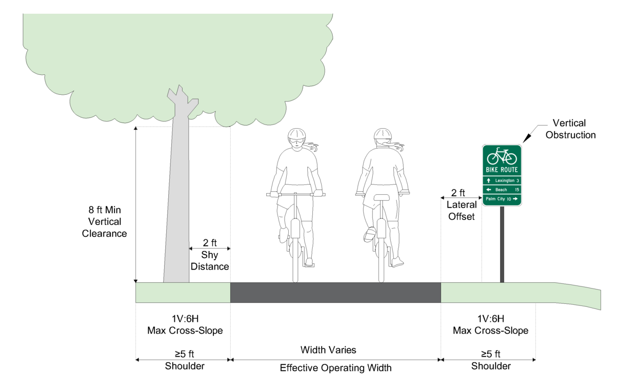
Source: Adapted from AASHTO Guide for the Development of Bicycle Facilities, Figure 6-5
Figure 11-2: Shared Use Path Shoulders, Continuous Shy Distance, and Barriers Adjacent to Hazards
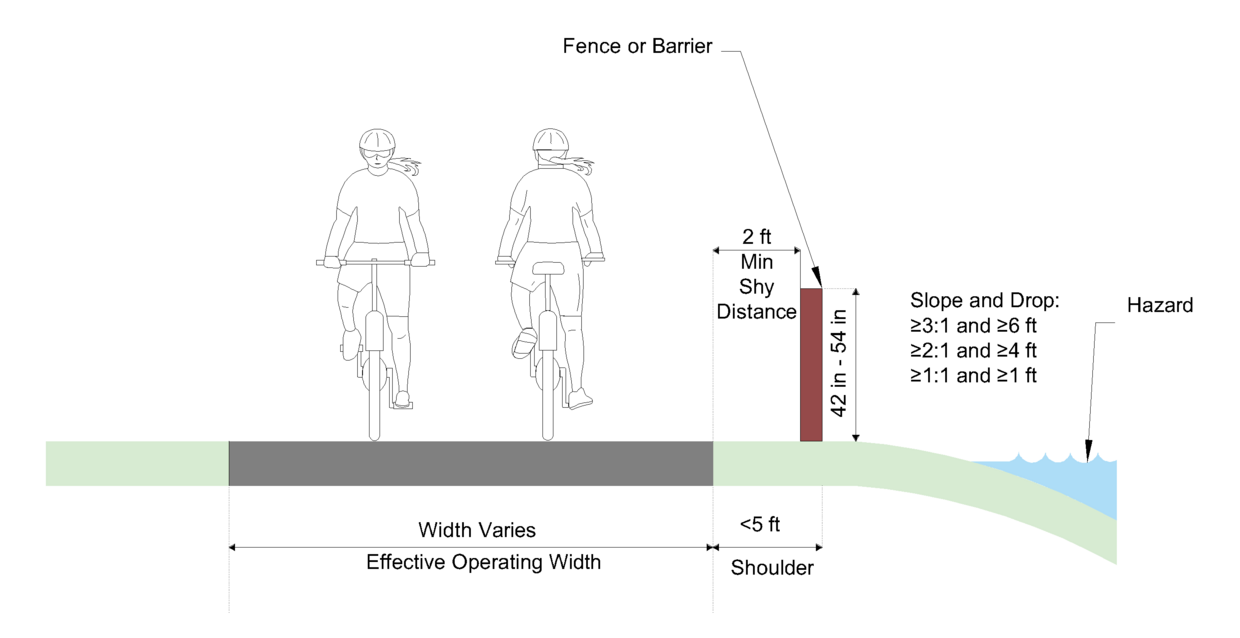
Source: Adapted from AASHTO Guide for the Development of Bicycle Facilities, Figure 6-7
Separation Between Sidepaths and Roadways
The shoulder and shy distance considerations of an independently aligned shared use path also apply to a sidepath. In addition, a sidepath requires a wide separation to the adjacent roadway to:
- Maximize path user safety and comfort when traveling adjacent to motor vehicle traffic
- Demonstrate to both the path user and the motorist that the path functions as an independent facility for path users
- Locate the sidepath outside the roadway clear zone where applicable
A 6-foot roadway buffer space between a sidepath and the adjacent roadway should be provided between the vertical element where a white edge line is not provided. When the sidepath is adjacent to on-street parking that provides separation from motor vehicle traffic, the buffer width can be reduced to 2 to 4 feet. A buffer of 4 feet is preferred to reduce passenger-side door-zone conflicts. A buffer is not required when the sidepath is located adjacent to a low-speed street (30 mph or less, posted or statutory) that does not include on street parking along the sidepath, and is separated vertically by a curb.
When conditions constrain the buffer width, a suitable physical barrier (considered to be one that does not obstruct sight lines, as identified in the “Barrier Height and Placement” section) is recommended. Such barriers serve both to prevent path users from making unwanted movements between the path and the highway shoulder and to reinforce the concept that the path is an independent facility.
Future signs, mailboxes, and other side obstructions should be considered when designing separation between the sidepath and roadway. Care should also be taken to provide adequate clearance along and between the path and adjacent parcels for future expansion and necessary buffers to adjacent land uses.
Vertical Clearance
The vertical clearance to obstructions should be a minimum of 8 feet, which meets the requirements of 521 CMR and the 2010 ADA Standards. In some instances, vertical clearance may need to be greater to permit passage of maintenance and emergency vehicles. See the “Underpasses and Vertical Clearance” section for a discussion of vertical clearances for underpasses.
One-Way Paths/Multiple Treadways
If a one-way shared use path is necessary to make a key connection, the minimum width should be 6 feet. A one-way path would rarely be designed and only in a special situation, such as to circumvent mature trees or connect to parallel paths. It should be recognized that one-way paths often will be used as two-way facilities unless effective measures are taken to assure one-way operation. Without such enforcement, it should be assumed that shared use paths would be used as two-way facilities by both pedestrians and bicyclists and designed accordingly.
In some cases it may be desirable to provide multiple treadways as part of a shared use path to separate user types to reduce potential conflicts, as illustrated in Figure 11‑3. Multiple treadways can be a successful design approach for heavily used corridors. In most applications of multiple treadways, a sidewalk or path suitable for pedestrians is provided separately from a path for bicyclists. Generally, the minimum width for the pedestrian path is 5 feet and the minimum width for the bicycle path is 10 feet.
Wider treadways are possible, and sometimes desirable, for both uses. The designer should take measures to ensure, however, that the purpose of each is clear to the users.
Figure 11-3: Cross Section of Shared Use Path with Multiple Treadways
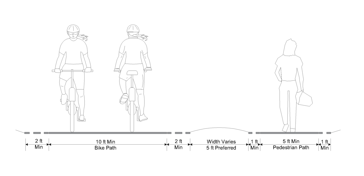
Source: Adapted from the Vermont Pedestrian and Bicycle Facility Planning and Design Manual
Barrier Height and Placement
The placement of physical barriers adjacent to a shared use path serves many purposes including safety and security, protection from falls, screening for adjacent land uses and separation of paths from other transportation facilities. The design of barriers is dependent upon their intended function, safety, proximity to the path, and aesthetics. The designer should determine the need to provide protection along a shared use path on a case-by-case basis after evaluating the following factors:
- If adequate recovery area is provided, then the need for a barrier is lessened.
- The greater the height of the drop-off, the greater the need for protection.
- 521 CMR requires ramps and landings with drop-offs shall have edge curbs, walls, railings, or projecting surfaces that prevent people from slipping off the ramp. Edge curbs shall be a minimum of two inches high.
- Where the side slopes are greater than 1V:3H, the need for a barrier is increased, unless the slope material is forgiving, or a recovery area is provided.
- If the material used on the side slope is grass, shrubbery, or another non-abrasive material, then the need for a barrier is lessened. If the material is likely to result in increased injury severity then the need for a barrier is increased.
Where used, the AASHTO Guide for the Development of Bicycle Facilities recommends that the barrier should be a minimum of 3.5 feet high to prevent bicyclists from toppling over it as previously shown in Figure 11‑2. A barrier between a shared use path and adjacent highway should not impair sight distance at intersections and should be designed to not be a hazard to motorists or bicyclists. A variety of barrier types are possible including:
- Fences – including a variety of fence types
- Retaining Walls
- Vegetation – for cushioning (such as shrubs, pine trees, etc.) capable of stopping a fall, spaced at most 6 feet on-center within 10 feet of the grade drop. This barrier type will require maintenance to ensure that the vegetation does not eventually encroach on the path.
- Guardrail or Concrete Barrier – placement of a rail on the top may be necessary to reach the required height. These barriers should meet the requirements of MASH if separating a path from a roadway.
Rub-rails to prevent snagging of handlebars are recommended at a height of approximately 36 inches to 44 inches from grade, as illustrated in Figure 11‑4. Other types of fencing with rub rails might be more architecturally appropriate, but split and round rail fencing present snag hazards and should not be used as rub rails. Additionally, the barrier systems should be smooth and free of protruding objects such as bolts. One method for reducing these hazards is to countersink washers and nuts into support posts, or mount a wood rail along the back side of the barrier. Barriers are recommended where the path:
- Has side slopes 1V:3H or steeper with a drop of 6 feet or greater
- Has side slopes 1V:2H or steeper with a drop of 4 feet or greater
- Has side slopes 1V:1H or steeper with a drop of 1 foot or greater
- Is adjacent to a parallel body of water or other substantial obstacles
Engineering judgement should be applied as the risk for a bicyclist who runs off the path should be compared to the risk posed by the physical barrier. The barrier should begin prior to and extend beyond the length of need to protect bicyclists from the adjacent hazard. The ends of the barrier should generally be flared away from the path edge. Consideration should be given to the possibility of a cyclist going off the path and behind the barrier toward the hazard. Barrier or railing ends that remain within 2 feet of the edge of path must be marked with object markers.
Figure 11-4: Barrier Elements
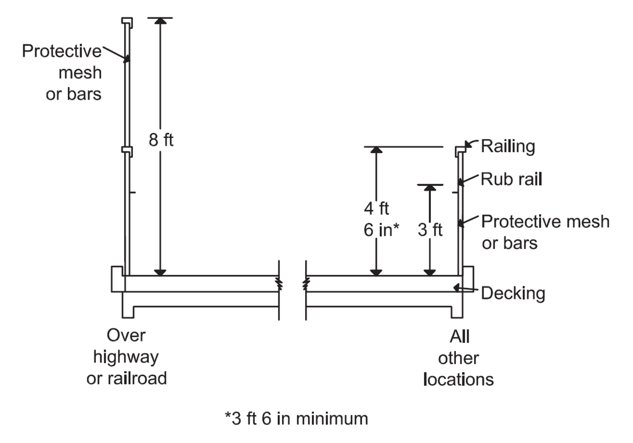
Source: Adapted from the Vermont Pedestrian and Bicycle Facility Planning and Design Manual
Design Speed
Shared use paths should be designed for a selected speed that is at least as high as the preferred speed of the faster bicyclists. In general, a minimum 20 mph design speed should be used. When a downgrade exceeds 4% or where strong prevailing tailwinds exist, a design speed of 30 mph or more is advisable. Lower design speeds, in the range of 10 to 15 mph, are appropriate for shared use paths through parks or other settings where the interactions between bicyclists and other users are frequent and unpredictable.
Cross-Slopes and Superelevation
Shared use pathways must meet the requirements of 521 CMR and the 2010 ADA Standards. Both of these standards require that cross slopes on pedestrian pathways and sidewalks not exceed 2 percent to avoid the dangers that greater cross slopes can create for people using wheelchairs, walkers, canes, etc. Thus, for most shared use paths, the maximum superelevation rate will be 2% in the built condition (1.5% in design). When transitioning a 2% superelevation, a minimum 25-foot transition distance should be provided between the end and beginning of consecutive and reversing horizontal curves.
Horizontal Curvature
The curvature of a path is dependent upon the design speed, lean angle and cross-slope of the path. Table 11‑1 summarizes the resulting curve radii for a range of design speeds using a 20-degree lean angle.
Table 11-1: Minimum Curve Radii
| Design Speed (mph) | Minimum Radius (ft) for Horizontal Curves at 20 Degree Lean Angle |
|---|---|
| 8 | 12 |
| 10 | 18 |
| 12 | 27 |
| 14 | 36 |
| 16 | 47 |
| 18 | 60 |
| 20 | 74 |
| 25 | 115 |
| 30 | 166 |
Source: AASHTO Guide for the Development of Bicycle Facilities, Table 6-5
It should be noted that 521 CMR does not allow curved ramps.
Sight Distance
To provide bicyclists with an opportunity to see and react to the unexpected, a shared use path should be designed with adequate stopping sight distances. Minimum stopping sight distance for various design speeds, vertical and horizontal curves, and grades need to be considered to ensure safe braking distance on a shared use path. The equation to calculate stopping sight distance is shown below. Table 11-2 and Table 11-3 provide stopping sight distance for various combinations of grade and design speed for reaction times of 2.5 and 1.5 seconds, respectively. A reaction time of 2.5 seconds is recommended at locations where potential conflicts or hazardous conditions are unexpected, such as a reduced width path in a tunnel, an approach to a hidden driveway, or in rural contexts. A reaction time of 1.5 seconds is recommended for locations where bicyclists have an expectation of potential conflicts, such as at intersections or on urban and suburban roadways. Bicyclists frequently ride side-by-side on shared use paths, and on narrow paths bicyclists tend to ride near the middle of the path. For these reasons, and because of the higher potential for head-on bicycle crashes, lateral clearances on horizontal curves should be calculated based on the sum of the stopping sight distances for bicyclists traveling in opposite directions around the curve.
Minimum Bicyclist Stopping Sight Distance
S = [V2/30(ıG)] + 1.47Vt
Where
- S = stopping Sight Distance (ft)
- V = velocity (mph)
- ƒ = coefficient of friction (0.16 for a typical bike in wet conditions)
- G = absolute value of grade (ft/ft) (rise/run)
- t = perception / reaction time (1.5 seconds for expected stops, 2.5 seconds for unexpected stops)
Note: ± = negative traveling downhill, positive uphill
Source: AASHTO Guide for the Development of Bicycle Facilities, Table 5-1
Table 11-2: Stopping Sight Distance (ft) Based on Speed and Grade for a 2.5 Second Perception-Reaction Time
| Speed (mph) | -10% Grade | -8% Grade | -6% Grade | -4% Grade | -2% Grade | 0% Grade | 2% Grade | 4% Grade | 6% Grade | 8% Grade | 10% Grade |
|---|---|---|---|---|---|---|---|---|---|---|---|
| 10 | - | - | - | 65 | 61 | 58 | 55 | 53 | 52 | 51 | 50 |
| 11 | - | - | - | 74 | 69 | 66 | 63 | 61 | 59 | 57 | 56 |
| 12 | - | - | - | 84 | 78 | 74 | 71 | 68 | 66 | 64 | 62 |
| 15 | - | - | 130 | 118 | 109 | 102 | 97 | 93 | 89 | 86 | 84 |
| 18 | 246 | 201 | 174 | 156 | 143 | 134 | 126 | 120 | 115 | 111 | 108 |
| 20 | 296 | 240 | 207 | 185 | 169 | 157 | 148 | 140 | 134 | 129 | - |
| 25 | 440 | 353 | 300 | 266 | 241 | 222 | 208 | 196 | 187 | - | - |
| 30 | 611 | 486 | 411 | 361 | 325 | 298 | 277 | 260 | - | - | - |
Note: calculations are assumed under wet conditions.
Source: AASHTO Guide for the Development of Bicycle Facilities, Table 5-2
Table 11-3: Stopping Sight Distance (ft) Based on Speed and Grade for a 1.5 Second Perception-Reaction Time
| Speed (mph) | -10% Grade | -8% Grade | -6% Grade | -4% Grade | -2% Grade | 0% Grade | 2% Grade | 4% Grade | 6% Grade | 8% Grade | 10% Grade |
|---|---|---|---|---|---|---|---|---|---|---|---|
| 10 | - | - | - | 50 | 46 | 43 | 41 | 39 | 37 | 36 | 35 |
| 11 | - | - | - | 58 | 53 | 49 | 47 | 44 | 43 | 41 | 40 |
| 12 | - | - | - | 66 | 61 | 56 | 53 | 50 | 48 | 46 | 45 |
| 15 | - | - | 108 | 96 | 87 | 80 | 75 | 71 | 67 | 64 | 62 |
| 18 | 220 | 175 | 148 | 130 | 117 | 107 | 100 | 94 | 89 | 85 | 81 |
| 20 | 267 | 211 | 178 | 155 | 139 | 128 | 118 | 111 | 105 | 100 | - |
| 25 | 403 | 316 | 264 | 229 | 204 | 185 | 171 | 159 | 150 | - | - |
| 30 | 567 | 442 | 367 | 317 | 281 | 254 | 233 | 216 | - | - | - |
Note: calculations are assumed under wet conditions
Source: AASHTO Guide for the Development of Bicycle Facilities, Table 5-3
The equation to calculate the minimum length of vertical crest curves to provide adequate stopping sight distance is below.
Length of Crest Vertical Curve to Provide Sight Distance Equations
When S > L
L = 2S [200(√h1+√h2)2] / A
When S < L
L = AS2 / 100(√2h1+√2h2)2
Where:
- L = minimum length of vertical curve (ft)
- A = algebraic grade difference (percent)
- S = stopping sight distance for flat grade (ft)*
- h1 = eye height (3.83 ft for a typical recumbent bicyclist)
- h2 = object height (0 ft)
*See Tables 11-2 and 11-3
Source: AASHTO Guide for the Development of Bicycle Facilities, Table 6-7
Table 11-4 provides the minimum curve length for crest vertical curves based on stopping sight distance and the algebraic grade difference for the vertical curve.
Table 11-4: Minimum Length of Crest Vertical Curve (ft) Based on Stopping Sight Distance for Flat Grade (ft) and Algebraic Grade Difference (%)
| % | 40 ft | 60 ft | 80 ft | 100 ft | 120 ft | 140 ft | 160 ft | 180 ft | 200 ft | 220 ft | 240 ft | 260 ft | 280 ft | 300 ft |
|---|---|---|---|---|---|---|---|---|---|---|---|---|---|---|
| 2 | - | - | - | - | - | - | - | - | 17 | 57 | 97 | 137 | 177 | 217 |
| 3 | - | - | - | - | - | 25 | 65 | 105 | 145 | 185 | 225 | 265 | 307* | 352* |
| 4 | - | - | - | 9 | 49 | 89 | 129 | 169 | 209* | 253* | 301* | 353* | 409* | 470* |
| 5 | - | - | 7 | 47 | 87 | 127 | 167* | 211* | 261* | 316* | 376* | 441* | 512* | 587* |
| 6 | - | - | 32 | 72 | 112 | 154* | 201* | 254* | 313* | 379* | 451* | 530* | 614* | 705* |
| 7 | - | 11 | 51 | 91 | 132* | 179* | 234* | 296* | 366* | 442* | 526* | 618* | 716* | 822* |
| 8 | - | 24 | 64 | 104* | 150* | 205* | 267* | 338* | 418* | 505* | 602* | 706* | 819* | 940* |
| 9 | - | 35 | 75 | 117* | 169* | 230* | 301* | 381* | 470* | 569* | 677* | 794* | 921* | 1057* |
| 10 | 3 | 43 | 84* | 131* | 188* | 256* | 334* | 423* | 522* | 632* | 752* | 883* | 1023* | 1175* |
| 11 | 10 | 50 | 92* | 144* | 207* | 281* | 368* | 465* | 574* | 695* | 827* | 971* | 1126* | 1292* |
| 12 | 16 | 56 | 100* | 157* | 226* | 307* | 401* | 508* | 627* | 758* | 902* | 1059* | 1228* | 1410* |
| 13 | 21 | 61* | 109* | 170* | 244* | 333* | 434* | 550* | 679* | 821* | 978* | 1147* | 1331* | 1527* |
| 14 | 25 | 66* | 117* | 183* | 263* | 358* | 468* | 592* | 731* | 885* | 1053* | 1236* | 1433* | 1645* |
| 15 | 29 | 70* | 125* | 196* | 282* | 384* | 501* | 634* | 783* | 948* | 1128* | 1324* | 1535* | 1762* |
| 16 | 32 | 75* | 134* | 209* | 301* | 409* | 535* | 677* | 836* | 1011* | 1203* | 1412* | 1638* | 1880 |
| 17 | 35 | 80* | 142* | 222* | 320* | 435* | 568* | 719* | 888* | 1074* | 1278* | 1500* | 1740* | 1997* |
| 18 | 37 | 85* | 150* | 235* | 338* | 461* | 602* | 761* | 940* | 1137* | 1354* | 1589* | 1842* | 2115* |
| 19 | 40* | 89* | 159* | 248* | 357* | 486* | 635* | 804* | 992* | 1201* | 1429* | 1677* | 1945* | 2232* |
| 20 | 42* | 94* | 167* | 261* | 376* | 512* | 668* | 846* | 1044* | 1264* | 1504* | 1765* | 2047* | 2350* |
* Area represents S<L. Minimum length of vertical curve = 5ft
Source: AASHTO Guide for the Development of Bicycle Facilities, Table 6-8
Designers should check that proposed K values for vertical curves meet the minimum values in Table 11-5.
Table 11-5: Minimum Rate of Vertical Curvature (K) for Bicycle Stopping Sight Distance on Crest Vertical Curves
| Design Speed (mph) | SSD (rounded) | Minimum Rate of Vertical Curvature, K | Minimum Rate of Vertical Curvature, K (rounded) |
|---|---|---|---|
| 10 | 50 | 2.8 | 3 |
| 12 | 60 | 4.0 | 4 |
| 15 | 80 | 7.1 | 7 |
| 18 | 100 | 11.1 | 11 |
| 20 | 120 | 16.0 | 16 |
| 25 | 160 | 28.4 | 28 |
| 30 | 205 | 46.7 | 47 |
Note: K values are calculated based on the 2012 AASHTO Guide for the Development of Bicycle Facilities Tables 5-4 and 5-5 and assume 0% grade and a friction coefficient of 0.32 for stopping sight distance.
Source: MassDOT
Where it is not possible or feasible to provide significant sight distance, consideration should be given to widening the path through the curve, installing a yellow center line stripe, installing a “Curve Ahead” warning sign in accordance with the MUTCD, or some combination of these alternatives. The designer can also consider clearing obstructions along the inside of the curve of the path to increase the available sight distance. AASHTO provides guidance on the appropriate clearance areas.
Grade
Where a bicycle path follows the existing terrain, Table 11‑6 offers guidance on the maximum grade lengths. Grades greater than 5 percent are undesirable because the ascents are difficult for many bicyclists and the descents cause some bicyclists to exceed the speeds at which they are competent or comfortable. Steep grades also do not meet pedestrian accessibility requirements.
Table 11-6: Maximum Grade Lengths for Bicyclists
| Grade (%) | Maximum Length (ft) |
|---|---|
| 5 to 6 | 800 |
| 7 | 400 |
| 8 | 300 |
| 9 | 200 |
| 10 | 100 |
| 11+ | 50 |
Source: AASHTO Guide for the Development of Bicycle Facilities, 1999
Grades for pathways used by pedestrians cannot exceed 5% unless treated as a ramp, with a maximum slope of 8.33% in the built condition. Even when shared with bicyclists, these pedestrian pathway slopes must be met, or a variance from 521 CMR must be granted from the Massachusetts Architectural Access Board. Variances should only be recommended with support from MassDOT, the local disability commission(s), and the regional Independent Living Center.
Path-Roadway Intersections
Intersections between paths and roadways are often the most critical issue in shared use path design. The following principles should be applied to the design of shared use path intersections and crossings to maximize safety and comfort for all users:
- Provide adequate sight distance and visibility
- Communicate right-of-way priority
- Minimize exposure to conflicts
- Reduce speeds at conflict points
- Maximize accessibility for users of all ages and abilities
A recessed (set back) crossing can reduce conflicts at crossings by creating space for the motorist to yield to approaching bicyclists followed by an additional space of approximately one car length to wait at the edge of the roadway to look for a gap in traffic without blocking the path. Raised crosswalks and refuge islands can be incorporated into the treatment to provide additional safety benefits. Figure 11‑5 provides an example of a recessed crossing at a shared use path intersection.
Figure 11-5: Recessed Crossing at Shared Use Path Intersection
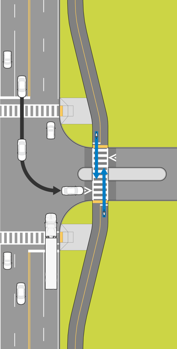
Source: MassDOT
It may be feasible or desirable in some locations to implement access management principles to improve overall traffic flow and safety within a corridor as well as to eliminate motorist conflicts with bicyclists. Figure 11‑6 provides an example of a recessed crossing combined with a median refuge to restrict motorist through crossings and left turns across the shared use path intersection.
Figure 11-6: Recessed Crossing at a Shared Use Path Intersection with Left Turn and Through Crossing Restrictions
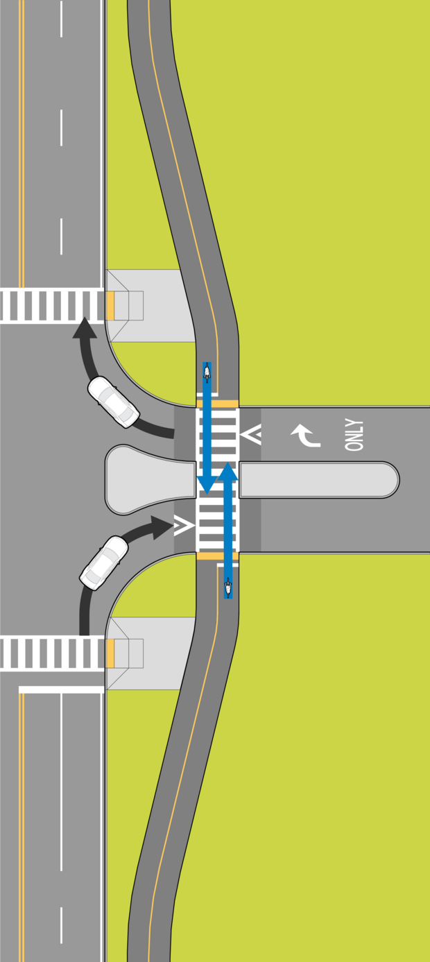
Source: MassDOT
Figure 11-7: Example of Diagonal Path Crossing at Signalized Intersection
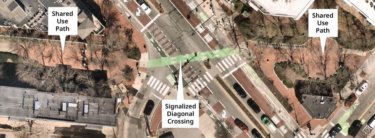
Source: Nearmap (Aerial), with Annotations by MassDOT
As the path approaches the crossing it should be aligned with the destination of the crossing on the other side of the road. Unless the destination is at a diagonal across the intersection, as shown in Figure 11‑7, the crossing should also be as perpendicular as possible to the road being crossed. Pedestrian curb ramps that comply with 521 CMR should be appropriately aligned and be the same width as the path (at least 36” plus the side flares). The designer should evaluate Stopping Sight Distance and Intersection Sight Distance and use sound engineering judgment to locate crossings. See “Sight Distance” in this chapter and Chapter 3, Section 3.7 Sight Distance for appropriate guidance on sight distances.
Midblock crossings of paths are also possible where adequate spacing from adjacent intersections is present. In many cases, it is desirable to provide a crossing island in the middle of a roadway when higher speeds or traffic volumes are present, as shown in Figure 11‑8. These islands can increase the visibility of the crossing, slow motor vehicle speeds on the cross-street, and provide a refuge for crossing path users. The islands should include pedestrian curb ramps or cut-throughs with detectable warning panels.
Figure 11-8: Example of Midblock Path Crossing with Crossing Island
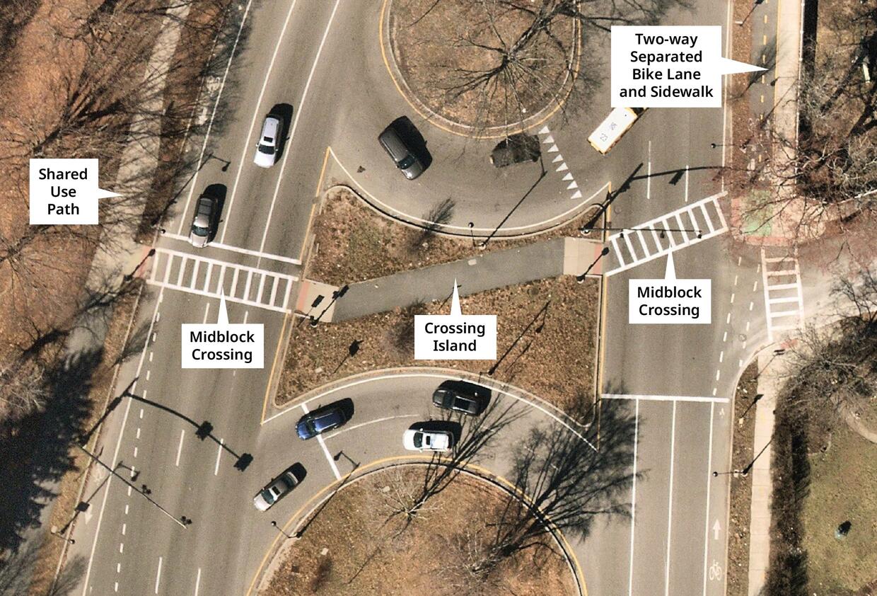
Source: Nearmap (Aerial), with Annotations by MassDOT
Traffic Control at Path Crossings
Path crossings can occur as signalized or unsignalized intersections, depending on the location. Warrants for signalization are discussed in the MUTCD and Warrant #4 should be used as guidance for path crossings as bicycles are considered pedestrians under these circumstances. If a crossing is located near a school, Warrant #5 may be applicable.
Where signals are provided, the path should be provided with MUTCD-compliant pedestrian crossing time phases to allow pedestrians and cyclists to cross the street. At locations with push-buttons, the signals should respond quickly to activation so that the likelihood of signal adherence is increased and a higher level of service is provided to the path. The U.S. Access Board’s Public Right-of-Way Accessibility Guidelines (PROWAG) require audible and vibrotactile walk indications where pedestrian signals are provided.
At unsignalized locations, adequate sight distance should be provided along the roadway approaches to the path and the path approaches to the roadway. In most cases, advance warning signs indicating that a pedestrian/bicycle path is crossing the roadway should be provided along the road in accordance with the MUTCD. In most cases, STOP signs are provided on the path approaches to the intersection. STOP AHEAD signs along the path may be appropriate if visibility to the crossing along the path is limited. STOP bars and centerlines should be provided on the path approaches to the crossing. The path crossing of the street should be marked as a crosswalk since it carries a mix of non-motorized users. Horizontal alignment changes along the path in advance of the crossing should be provided to reduce the speeds of people biking approaching the intersection. Other design cues such as painted medians should be evaluated. Due to the potential conflicts at these junctions, careful design is of paramount importance to the safety of path users and motorists. Each intersection is unique and will require sound engineering judgment on the part of the designer as to the appropriate solution. The AASHTO Guide for the Development of Bicycle Facilities provides examples and guidelines for various intersection treatments. Path crossings of roadways are also discussed further in Chapter 6.
Grade Separation of Path Crossings
There is often a desire to grade separate the crossings of highly-utilized paths and busy roads. In these cases, both underpasses and overpasses are options. The topography of the surrounding area usually will govern which type of grade separation is selected. In level terrain, an underpass usually requires shorter ramp sections since the path clearance under a road ranges between 8 and 12 feet. Road or railroad clearance under a path, on the other hand, can range from 17 to 23 feet. If the path is designed with a maximum five-percent slope, then the transitions for an overpass can be twice as long as those for an underpass (as much as 500 feet in each direction). On the other hand, overpasses are generally open and have fewer security concerns.
While there are no clear “warrants” for grade separation of path crossings of roadways. The designer should consider a number of factors including:
- The suitability of the existing topography for grade separation
- The effectiveness of signage or traffic signal control as an alternative for the crossing given the context of the location
- Any changes in alignment that may be necessary to achieve the grade separation
- The opportunities or limitations placed on path connectivity to the surrounding area by the grade separation
- The context in which the path is set, in consideration of safety and security issues
- The volume, mix of vehicles, and speed of cross-traffic on the roadway
- The volume and mix of path users
If the grade separation adds out-of-direction travel to the path alignment or inconvenience, users will likely cross the roadway at grade, potentially eliminating the safety benefit of the grade separation. Furthermore, for shared use paths, pedestrians generally prefer at-grade treatments, so adequate provisions may be necessary for these crossings even if grade separation is provided.
Bridges, Overpasses, and Underpasses
A shared use path may also cross a natural feature, such as a stream or river, on a bridge. Design elements of these structures are described below.
Bridges and Overpasses
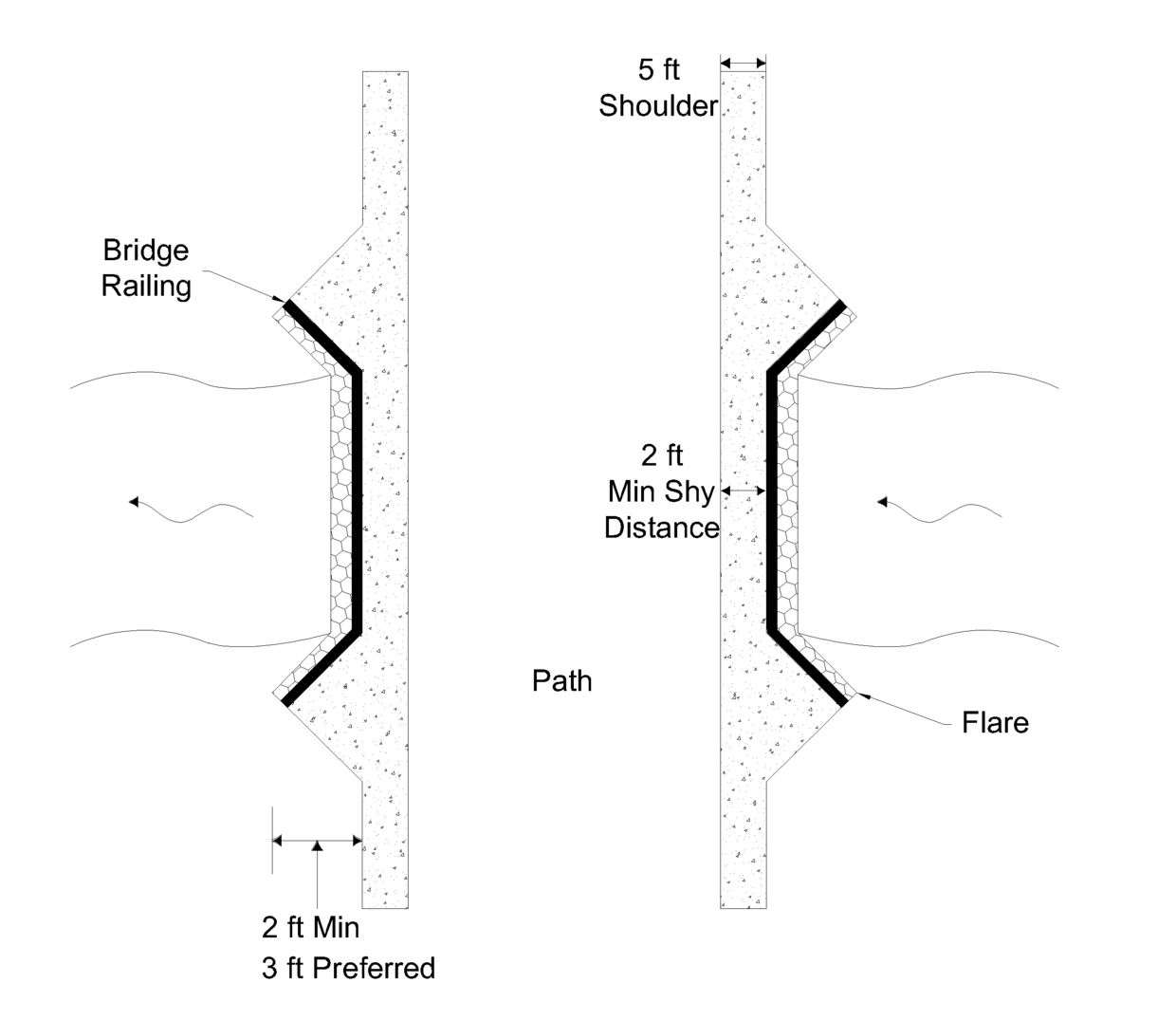
On a bridge or overpass, the effective operating width of the shared use path should remain consistent and the 5' shoulder requirement can be reduced to 2' to provide the minimum necessary shy distance from a continuous vertical element. The bridge railings should also be flared with an apron to direct path users onto the structure, as illustrated in Figure 11‑9. Vertical transitions to and from the bridge should follow the grade guidelines discussed earlier in this chapter. The maximum slope and cross slope standards in 521 CMR apply to bridges and overpasses. Therefore, any slope greater than 5% must be treated as a ramp, with handrails and level landings; and any slope greater than 8.33% is not allowed without a variance from the Massachusetts Architectural Access Board.
Figure 11-9: Bridge Treatments for a Path
Source: Adapted from the Vermont Pedestrian and Bicycle Facility Planning and Design Manual
The AASHTO Guide for the Development of Bicycle Facilities recommends that railings, fences, or barriers on both sides of a path on a structure should be a minimum of 42 inches (3.5 feet) high. In situations where the structure crosses a high-speed or high-volume road or objects are subject to being thrown off the structure, it is recommended that the path be enclosed with fencing. Enclosing a path may also be desirable in other areas such as a waterway crossing. However, to the extent feasible, clear views along the path crossing should be preserved to retain the aesthetics of the path’s environment.
Underpasses and Vertical Clearance
Underpasses and tunnels should meet the same effective operating width and side clearance requirements as bridges and overpasses. Vertical clearance of at least 8 to 12 feet should be provided. In underpasses and tunnels, 10 feet is desirable for adequate vertical shy distance (the vertical clearance at which a bicyclist would feel comfortably separated from an obstruction) and passage by maintenance vehicles. A typical arrangement of a path underpass is illustrated in Figure 11‑10. See also “Vertical Clearance” for a general discussion of vertical clearances for obstructions.
Figure 11-10: Path Underpass
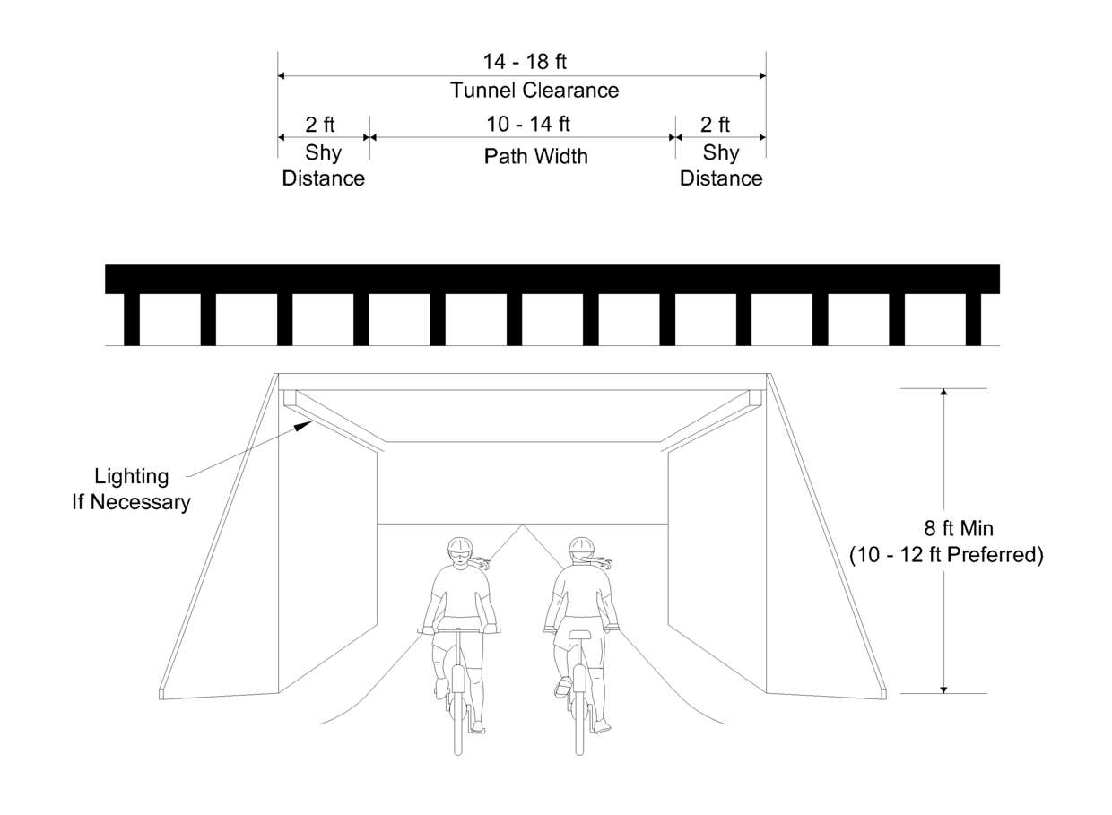
Source: Adapted from the Vermont Pedestrian and Bicycle Facility Planning and Design Manual
Signing and Marking
Adequate signing and marking are essential on shared use paths, especially to alert bicyclists to potential conflicts and to convey regulatory messages to both bicyclists and motorists at highway intersections. Both advanced crossing and crossing warning signs are needed on roadways to provide appropriate warning to the motorists of the upcoming path intersection. In addition, guide signing on a path, such as to indicate directions, destinations, distances, route numbers, mile markers (to aid in emergency response), and names of crossing streets, should be used in the same manner as they are used on highways. Where the Massachusetts Architectural Access Board (MAAB) has granted variances for steeper slopes on walkways, it is useful to provide signage indicating the length and difficulty of the trail. This will allow people with disabilities or limited stamina to decide how much time do they need, which route they want to take, and what assistance might be needed to experience the sites of the trail.
For additional guidance refer to the Bike Wayfinding Design Guide.
In general, uniform application of traffic control devices, as described in the MUTCD, provides minimum traffic control measures that should be applied. Warning signs, directional signs, and other devices along the path should also meet the MUTCD guidelines. The MUTCD requires a minimum 2-foot lateral clearance to signs and sign supports. This clearance should be measured from the outside edge of the shoulder.
The application of traffic control at path/roadway crossings is described in the “Path-Roadway Intersections” section.
Surfacing
When selecting paving and surfacing materials, long-term durability, safety, availability, cost and maintenance are important selection criteria. All paths need to provide a firm, stable, slip-resistant surface in a wide variety of use and weather conditions. In general, surfacing materials for paths in urban areas should be paved or consist of other “hard-surface” materials. Paved pathways function best in areas with high use and those that will be cleared of snow in the winter.
Where pedestrians are intended pathway users, accessibility of the surface is a key factor. Both 521 CMR and the 2010 ADA Standards require that the surface be:
- Firm, stable, and slip-resistant
- Without slopes and cross slopes greater than the maximum allowed. The Massachusetts Architectural Access Board measures compliance of slopes in 24-inch increments using a digital level. This can be a difficult standard to meet at first construction and over the life of the pathway
- Without level changes of greater than ¼”. Rippled asphalt and tree roots protruding through pathway surfaces create undesirable conditions for people with disabilities
- Without low-hanging branches or other obstacles that protrude into the accessible route between the heights of 27” – 80”. These are undesirable conditions for people using the facility, especially for those with disabilities
For paved paths, a subbase of compacted aggregate or structurally suitable soil is important to ensure the long-term durability of the pavement. Figure 11‑11 illustrates a typical pavement design for a path. In most cases, a 4-inch bituminous concrete riding surface placed over an 8 to 12-inch aggregate base is recommended, especially if the path needs to support occasional maintenance or emergency vehicles. The designer must consider the site-specific soil, environmental, and use characteristics of the path when determining the appropriate pavement design.
Some surface treatments may be appropriate to introduce a particular theme or gain a certain aesthetic quality for a shared use path. Both 521 CMR and the 2010 ADA Standards require that accessible elements be maintained. Finally, where a paved path intersects gravel roadways and driveways, 10-foot paved aprons on the roadway or driveway approaches are recommended to keep debris off the path and minimize pavement damage.
Tree roots often contribute to sidewalk and path pavement degradation and failure. Project design should include site analysis of soil conditions as well as existing and proposed trees to determine risk of encroachment and make recommendations for both tree management as well as pavement protection.
Path shoulders should also provide a smooth area that resists erosion, root intrusion, debris spreading and other undesirable effects. Grassed shoulders are very common along shared-use paths, but require mowing and other regular maintenance. Stone dust shoulders are another option that the designer may consider.
Figure 11-11: Typical Path Pavement Design
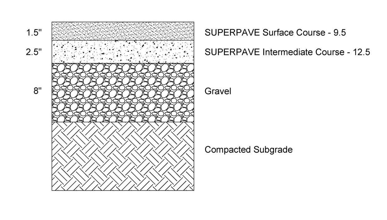
The thickness of the asphalt layers shown in Figure 11-11 can be increased at locations where heavy vehicle access (maintenance and emergency vehicles) are expected to be on or crossing the pathway. Consult the MassDOT Pavement Design Engineer when considering adjusting the thickness of HMA layers.
Source: MassDOT
Landscape Selection and Maintenance
Selecting appropriate landscaping vegetation and then maintaining the landscaped vegetation that is chosen and installed are important aspects of path and trail design. Refer to Chapter 13 for more discussion of landscaping.
Drainage
The maximum allowable pavement cross slope of 2 percent adequately provides for drainage. However, lower design cross-slopes may be needed to ensure compliance with 521 CMR and AADAG regulations in the built condition. Sloping in one direction instead of crowning is preferred and usually simplifies the drainage and surface construction. A smooth surface is essential to prevent water ponding and ice formation. On unpaved paths, particular attention should be paid to drainage to avoid erosion. Where the path is constructed on a hillside, ditches of suitable dimensions to contain the flow of water from the uphill side of the path should be constructed. To prevent erosion, paved waterways should be provided at low points and berm should be provided on the edge of steep slopes along the shoulder and resulting drop-off. In areas with underground drainage systems, catch basins should be located outside of the path and flush with its surface. Bicycle-safe, wheelchair-safe, and crutch-safe drainage grates should be used exclusively.
Lighting
Lighting for shared use paths is important and should be considered where night usage is expected, such as paths serving college students or commuters, and at highway intersections. Lighting should also be considered through underpasses or tunnels and when nighttime security could be an issue.
Restriction of Motor Vehicle Traffic
Shared use paths may need some form of physical barrier at roadway intersections to prevent unauthorized motor vehicles from using the facilities. Treatments should maintain emergency access. Provisions can be made for a lockable, removable (or reclining) barrier post to only permit entrance by authorized vehicles.
Signs, median landscape islands, splitter islands and flexible delineator posts are the preferred control measures. Bollards and P-gates should only be considered when all other methods have proven unsuccessful. Regardless of the type of physical barrier used, it should be maintained to ensure that it does not become a safety issue. A short splitter island (Figure 11-12) should be designed to maintain a minimum of 5 feet on either side of the island. If a sidewalk is present, the splitter island should be set behind the sidewalk. If the splitter island is landscaped, the plantings should be low height such that the island can be traversed by an emergency vehicle and does not obstruct sight lines.
Figure 11-12: Splitter Island Treatment
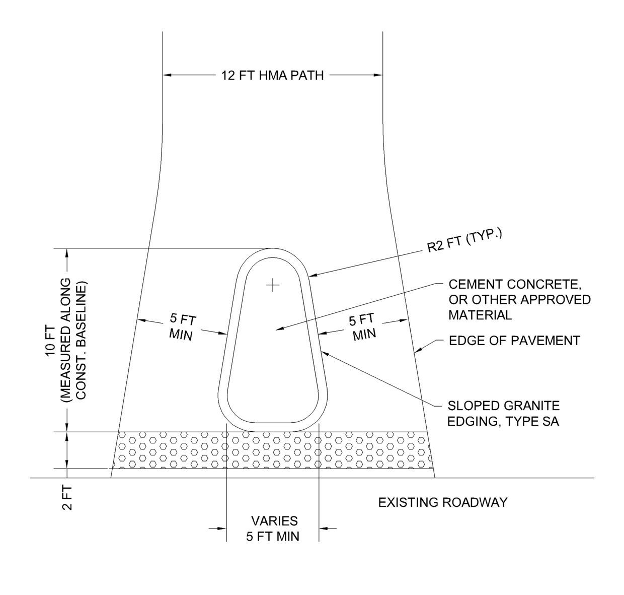
Source: MassDOT
Bicycle Parking
Bicycle racks are an integral part of accommodating bicycle transportation. Bicycle racks should be located where they are convenient to the users and where they will not interfere with pedestrian and vehicular traffic. Providing bicycle racks helps discourage users from locking bikes to railings, street trees, and other furnishings. General guidelines are presented below:
- The appropriate number of spaces needed should be assessed with respect to the associated building or land use
- Typical inverted “U” systems are preferred, but any similar rack that meets the following criteria may be used:
- Rack must enable the frame and one or both wheels to be secured, preventing the bike from tipping over
- The rack should be anchored so that it cannot be stolen with bikes attached
- Two locking points available for theft-protection
For parallel storage, arrange rack elements 30 inches on center to allow space for two bicycles to be secured to each rack element. For additional guidance, refer to the Association of Pedestrian and Bicycle Professionals “Essentials of Bike Parking” and Chapter 13, Section 13.4 " Bicycle Racks" subsection.
11.5 Rail Trails
Railroads developed a vast network of transportation corridors throughout the region. Many of these corridors no longer serve railroad activities and many still do. Regardless of the actual presence of railroad activity in a corridor, railroad rights-of-way (ROW) are often seen as opportunities for the development of shared use paths. The design elements of shared use paths described earlier in this chapter are applicable to rail trails. Although not discussed in detail below, rail trails can also be developed as more primitive trails, or for use by motorized vehicles such as snowmobiles.
Inactive ROW
Inactive ROW serve as ideal candidates for the development of formalized shared use paths and for informal use by other users such as snowmobiles and cross-country skiers. The railroad ROW is generally suitable for reuse as a shared use path because the geometric features of the railroad, such as grades, alignment, clearances, etc. are also favorable for use by pedestrians, bicyclists, and others. The key differences between developing a shared use path on an inactive railroad ROW versus a new alignment include:
- Property issues are sometimes complicated along railroad rights-of-way, especially those that have been long-abandoned by the railroad.
- Existing structures, road crossings, and other features may be suitable for re-use.
- The ROW may provide access to new recreational or other resources, not well served by the roadway network.
- The ROW may be highly separated from the surrounding urban or natural environment, facilitating through movement, but complicating connections to surrounding attractions and destinations.
- There is a reasonable expectation of hazardous material contamination, especially in former railroad yard areas.
- Redevelopment of the ROW may pose a real opportunity for economic growth and revitalization of adjacent properties.
Rails with Trails
The development of shared use paths adjacent to active railroads is often more controversial than the reuse of inactive ROW. Railroad companies may not enthusiastically embrace the concept of a shared use path adjacent to their facility. Railroad corridors are usually private property and are viewed as frequented by trespassers, who are often responsible for vandalism or accidents. There is often a concern that development of a path will increase the amount of this undesirable activity. With these challenges in mind, it is understandable that railroad owners and operators may be hesitant to support path development near their facilities, however, introducing formal trail use within the ROW can lead to a reduction in undesirable activities as well as a reduction in illegal dumping by abutters or outsiders.
There is often width within a railroad ROW that is not being actively used for railroad purposes. These corridors can be opportunities for path development. The key considerations in the development of paths within active railroad corridors are the ability to provide adequate separation between the railroad activity and the shared use path as discussed below.
Separation from Railroad Operations
According to the FRA and FHWA’s Rails-with-Trails: Best Practices and Lessons Learned, the setback between the path and the railroad should take into consideration the speed and frequency of trains in the corridor, maintenance activities, separation techniques, existing problem areas, and good judgment. However, the required setback is ultimately determined by the railroad owner. In areas where required setbacks cannot be achieved, additional right-of-way should be acquired, or additional separation measures should be established to improve security and ensure safety.
As an absolute minimum, the path cannot fall within the train’s envelope of operation, which is the space required for the train and its cargo to overhang due to any combination of loading, lateral motion, or suspension failure. Separation between the track and the path is illustrated in Figure 11‑13. Recommended separation widths and barrier needs in Table 11‑7 vary based on the type of rail operation and the setting characteristics. Types of rail operations include:
- High volume/high speed – 11 trains or more per day with max speed over 45 mph
- Medium volume/medium speed – Fewer than 11 trains per day with max speed 45 mph
- Low volume/low speed – Fewer than 1 train per day with max speed 35 mph
Exceptions to separation recommendations are possible on a negotiated, case-by-case basis with the track owner/operator.
Methods to provide additional width for path development within a constrained existing railroad ROW are possible through selection of the path location or modification of the ROW cross-section. These methods are illustrated in Figure 11‑14 and include:
- Locate the path at the bottom of the slope
- Locate the path in an adjacent utility corridor
- Widen the embankment
- Excavate and retain the side-slopes
- Cantilever the path at rail trail bridge crossing, or provide a separate crossing independent of the rail bridge
- Use a low retaining wall.
Figure 11-13: Separation between Track and Path
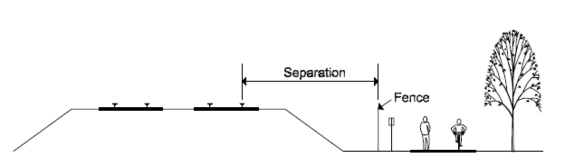
Source: Adapted from the Vermont Pedestrian and Bicycle Facility Planning and Design Manual
Table 11-7: Recommended Separation between Active Rail Lines and Paths
| Type of Rail Operation | Setting Characteristics | Recommended Minimum Separation |
|---|---|---|
| High volume/high speed | Typical conditions | 25 feet with fence or 15 feet with a solid barrier |
| High volume/high speed | Constrained areas (cut/fill, bridges, etc) | 15 feet with fence or other physical barrier |
| High volume/high speed | Vertical separation of at least 10 feet | 20 feet |
| Medium volume/medium speed | Typical conditions | 25 feet or 15 feet with a physical barrier |
| Medium volume/medium speed | Constrained areas | 11 feet with a physical barrier |
| Medium volume/medium speed | High trespassing areas | 11 feet with a physical barrier |
| Low volume/low speed | Typical conditions | 25 feet preferred, 11 feet minimum |
| Low volume/low speed | Constrained areas | 11 feet with a physical barrier |
Source: Vermont Agency of Transportation Pedestrian and Bicycle Facility Planning and Design Manual
Figure 11-14: Methods to Provide Additional Width for Path Development
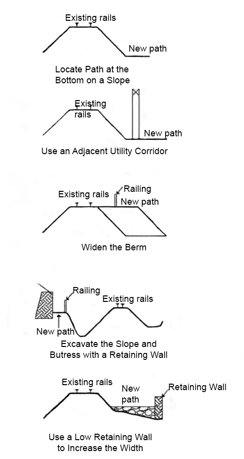
Source: Adapted from the Vermont Agency of Transportation Pedestrian and Bicycle Facility Planning and Design Manual
11.6 Maintenance
Maintenance is an important consideration for all transportation facilities including on-road bicycle facilities and shared use paths. Good maintenance practices, such as periodic sweeping, surface repairs, tree pruning, mowing, trash removal, litter pick-up, new pavement markings, etc., are important elements of a routine maintenance schedule. In addition, both the MAAB and the ADA require that accessible elements be maintained to meet their minimum standards.
Path maintenance operations are often undertaken by the locality or governing agency and their importance and the associated costs should be considered during the planning stages of the project. The entity who is to take on these responsibilities should be established early in the process. In some instances, nonprofit groups, civic groups, and private organizations (i.e. bike clubs) partner with the locality by assisting in the smaller maintenance tasks. Key maintenance activities are discussed below.
Sweeping and Debris Removal
Sand and gravel accumulation on a path can pose a serious hazard to cyclists and skaters. Paths should be periodically swept to avoid accumulation of debris. The sweeping schedule should be established based on the path conditions and needs. At a minimum, it is recommended that a path be swept six times per year.
Pavement Quality and Striping
Path users are particularly sensitive to pavement irregularities and paths should be regularly maintained to ensure that cracks, potholes and other pavement defects are corrected. Additionally, most paths require periodic restriping to ensure the visibility and effectiveness of pavement markings. Missing and damaged signs should also be replaced.
Snow Removal
Snow removal is required if a path will be used in the winter months. Many paths are used for walking, jogging, and cycling year-round. To accommodate these uses, snow should be placed well beyond the path (or marked shoulder lane) edge to avoid ice formation and other hazards. Fences and barriers should be sufficiently set back to allow effective snow removal.
In some cases, snow may not be removed to allow use of the path for cross-country skiing. A management decision should be made in consultation with the local entity and user groups to determine the preferred wintertime use.
11.7 For Further Information
For further information on the design of shared use paths, consult the following publications:
- A Policy on Geometric Design of Highways and Streets, AASHTO, 2018
- Guide for the Development of Bicycle Facilities, AASHTO, 2024
- Guide for the Planning and Design of Pedestrian Facilities, AASHTO, 2004
- Manual on Uniform Traffic Control Devices, Federal Highway Administration, 2009
- Rails with Trails, Lessons Learned, Federal Highway Administration, 2002
- MassDOT Policy Directive P-98-003 Bicycle Route and Share the Road Signing Policy
- MassDOT Separated Bike Lane Planning & Design Guide, 2015
- MassTrails Bike Wayfinding Design Guide, 2022
- MassTrails Website, 2023
- MassTrails Shared Use Path Planning Primer, 2018
- Accessible Rights of Way: A Design Guide, Architectural and Transportation Barriers Compliance Board, (Draft) 1999
- U.S. Department of Justice, ADA Standards for Accessible Design, 2010, Washington, D.C.
- Association of Pedestrian and Bicycle Professionals. Essentials of Bike Parking: Selecting and installing bicycle parking that works, 2015
- Vermont Pedestrian and Bicycle Facility Planning and Design Manual, 2002