7.1 Introduction
Due to safety concerns, operational concerns, spatial constraints, or other conditions, it is not always desirable to accommodate all users within an at-grade intersection. In these cases, an interchange – an overpass bridge or underpass structure to separate the intersecting facilities, connected by ramps – should be studied. An interchange can often provide the greatest safety and capacity; however, interchanges may not fit well within the existing context and may complicate multimodal accommodation.
As discussed in Chapter 6, it is important that designers consider the needs and activities of pedestrians, cyclists, and motorists to comprehensively plan for safe and convenient travel through intersections.
This chapter focuses on interchanges to provide connectivity between facilities. Grade separations without connecting ramps are discussed in Chapter 10, Bridges.
7.2 Warrants and Planning Considerations
Interchanges and grade separations are a crossing of two roadways, a roadway and a railroad, or a roadway and a pedestrian or bicycle facility, at different levels. Interchanges and grade separations eliminate crossing conflicts and improve operational efficiency. Grade separations alone do not provide connections or access between the intersecting roadways. Rather, motor vehicles, cyclists, and pedestrians on each intersecting roadway remain completely independent from the travelers on the other roadway. Interchanges provide access between the grade-separated roadways by incorporating a network of ramps. Roadways employing interchanges are often freeways and major arterials, also referred to as "highways" throughout this chapter. The following sections describe warrants and planning considerations for interchanges.
Warrants
In many instances, the decision to provide a grade-separated interchange should be based on careful consideration of six factors. These factors are referred to as “warrants” and include:
- Design Designation: Once it is decided to develop a route as a freeway, designers should determine whether each intersecting highway will be terminated, rerouted, or provided with a grade separation or interchange, the chief concern being continuous flow on the freeway.
- Reduction of Bottlenecks or Spot Congestion: Insufficient capacity at the intersection of heavily-traveled routes results in intolerable congestion to one or all approaches. Inability to provide essential capacity with an at-grade facility provides a warrant for an interchange where development and available right-of-way permit. Even on facilities with partial control of access, the elimination of signalization contributes greatly to improvement of free-flow characteristics.
- Reduction of Crash Frequency and Severity: Some at-grade intersections have a disproportionate frequency of serious crashes. If inexpensive methods of reducing crashes are likely to be ineffective or impractical, a highway grade separation or interchange may be warranted. Higher crash frequencies are often found at intersections between comparatively lightly-traveled highways in sparsely developed rural areas where speeds are high. In such areas, structures can usually be constructed at lower cost compared with urban areas, right-of-way impacts are typically less than in more-developed areas, and these lower-cost improvements can be justified by reducing only a few serious crashes, as is the case on lightly-traveled roads. Serious crashes at heavily-traveled intersections may also warrant interchange facilities. In addition to the reduction in crash frequency and severity, the operational efficiency for all traffic movements is also improved at the interchange.
- Site Topography: At certain sites, a grade-separated interchange may be more feasible than an at-grade intersection due to local topographical conditions.
- Traffic Volume: Interchanges are desirable at cross streets with heavy traffic volumes. The elimination of conflicts due to high crossing volume greatly improves the movement of traffic and reduces the likelihood of conflicts. A traffic volume warrant for interchange treatment may be the most tangible for any interchange warrant. Although a specific volume of traffic at an intersection cannot be completely rationalized as the warrant for an interchange, it is an important guide, particularly when combined with the traffic distribution pattern and the effect of traffic behavior. However, volumes in excess of the capacity of an at-grade intersection would certainly be a warrant.
- Road-User Benefits: When interchanges are designed and operated efficiently, they significantly reduce the travel time and costs when compared to at-grade intersections. Therefore, an interchange is warranted if an analysis reveals that road-user benefits will exceed costs over the interchange’s service life. The assessment of road-user benefits should consider impacts to multimodal users.
Additional reasons for constructing interchanges include the need to provide access to areas not served by other means, such as High Occupancy Vehicle (HOV) facilities, highway rest areas, tourist information centers, and highway maintenance facilities.
Contextual Considerations for Interchanges
In all cases, the designer should consider the relationship between the proposed interchange and the surrounding context, as described below.
- Does a grade separation currently exist?
- How does the proposed interchange fit within the cultural, historical, aesthetic, and environmental character of the surrounding area?
- Is sufficient right-of-way owned or controlled to construct and maintain the interchange? If not, is land available for acquisition to accommodate the project?
- Does the existence of a high ground water elevation and/or poor soil conditions complicate the design and construction of the required structures?
- If highway illumination is required to maintain adequate lighting levels for safety and/or security, is there a power source available to satisfy this need? Is such lighting consistent with the surrounding context?
- Will introducing continuous high-speed traffic or increased roadway grades create high noise levels requiring the introduction of noise barriers?
- Will the interchange result in substantial air quality improvements? Is mechanical ventilation required due to the physical and operational characteristics of the facility?
- Will construction impact existing utility systems? Are provisions for future utilities required by area municipalities, agencies, and/or public and private utility companies?
- Will elevating one roadway over another infringe upon abutter air rights or impact the operation of a nearby airport?
- Are there unique requirements relative to horizontal and vertical clearances and/or utility crossings associated with the proposed grade separation?
- Has the diversion of some or all activity been considered, thereby eliminating the need for grade separation?
- Will detours be required during construction, and are existing routes available? Will temporary detour roadways, bridges, or staged construction be required?
Pedestrian and Bicycle Accommodation Through Interchanges
Pedestrian and bicycle accommodation should be maintained through interchanges. In most cases, interchanges are provided between Interstate Highways and other roadways (referred to as the “minor road”). The pedestrian and bicycle accommodation, such as sidewalks, bicycle lanes, and shoulders on the minor road should be maintained through the interchange area. If pedestrian and bicycle use is permitted on both roadways, then this principle applies to both facilities.
Pedestrian and bicycle accommodation through interchanges is described throughout this chapter. A key factor for maintaining the continuity and safety of pedestrian and bicycle accommodation through interchanges is the configuration of the ramp/minor road intersection described in Section 7.7 Ramp Design. As described in this section, diamond-type ramps and signalized ramp terminals are preferable in areas with high pedestrian and bicycle activity.
In some instances, it may be preferable to provide a pedestrian and bicycle crossing of a limited-access roadway separate from an interchange, such as an overpass or underpass parallel to the route approaching the interchange. This could be a smaller street without an interchange or a dedicated bicycle and pedestrian crossing.
Interchanges Selection Factors
The decision to provide a grade separation without ramps rather than an interchange is often based on the following considerations:
- Lacking a suitable relocation plan for the crossroad, a highway grade separation without ramps may be provided to maintain connectivity of low-volume roadways. All users desiring to access one facility from the other are required to use other existing routes. In some instances, these users may have to travel a considerable distance, particularly in rural areas.
- Promotion of access to areas not served by frontage roads or other means of access, physically separating railroad grade crossings, providing access to HOV facilities, providing access to concentrations of pedestrian traffic (for instance a park developed on both sides of a major arterial), and allowing the passage of bicycles.
- A grade separation without interchange ramps may be provided to avoid having interchanges so close to each other that signing and operation would be difficult. This approach eliminates interference with large major road interchanges and increases safety and mobility by concentrating turning traffic at a few points where it is feasible to provide adequate ramp systems. On the other hand, undue concentration of turning movements at one location should be avoided where it would be better to have additional interchanges.
- In rugged topography the site conditions at an intersection may be more favorable for provision of a grade separation than an at grade intersection. If ramp connections are difficult or costly, it may be practical to omit them at the structure site and accommodate turning movements elsewhere by way of other intersecting roads.
- Many times, partial interchanges are constructed initially because the traffic volumes do not support a full interchange, or the required right-of-way is not available when the interchange is first constructed. As time passes however, the need for a complete interchange may develop or the right-of-way may be obtained.
Application to Freeways and Highways with Full Access Control
When full access control is proposed for an existing highway, or a new freeway is proposed, each intersecting public or private way must be handled using one of the following options. The options listed below also apply to pedestrian and bicycle facilities.
- The intersecting facility can be dead-ended effectively terminating through traffic
- The intersecting facility can be re-routed to maintain connectivity
- The intersecting facility can be grade separated as either an underpass or an overpass, maintaining through traffic but effectively terminating access to the intersecting highway
- The intersecting facility can be reconstructed as an interchange, to maintain through traffic access to the freeway
The importance of the continuity of the crossing road or the feasibility of an alternate route will determine whether a grade separation or interchange is warranted. An interchange should be provided on the basis of the anticipated demand for access to the minor road and the operational effects on the major roadway.
Interchange Spacing
Interchange spacing is an important consideration in the planning and design of new or modified interchanges. Interchange spacing is the distance measured along the main roadway between the centerlines of the intersecting roadways that maintain ramp access to the through highway.
In urban areas, there should be a one-mile minimum spacing between interchanges to allow sufficient space for entrance and exit maneuvers. Closer spacing may require the use of collector-distributor roads to remove the merging/diverging and accelerating/decelerating traffic from the freeway mainline.
In rural, undeveloped areas, interchanges should be spaced no closer than two miles apart, and no closer than three miles apart for Interstate highway interchanges. These spacing guidelines are intended to minimize the disruption of entering and exiting traffic to the mainline of the highway and to prevent insufficient sign spacing.
Interchange Justification/Modification Reports
The design and construction of interchanges or grade separations along Interstate highways is controlled by the Federal Highway Administration (FHWA) and requires their approval and conformance to their requirements regarding modifications to and maintenance of the Interstate system. An Interchange Justification Report (IJR) / Interchange Modification Report (IMR) is required for new interchanges or modifications to existing interchanges.
The designer should consult with FHWA for their latest policy for preparing an IJR/IMR. The policy is applicable to new or revised access points to existing Interstate facilities.
The following is a description of the information typically included in an IJR or IMR submitted to the FHWA:
- A clear description of the location and type of proposed new or modified access. Maps, schematic diagrams, and preliminary design plans should be included as needed to clearly describe the proposal. Drawings and plans should include (as applicable): project limits, adjacent interchanges, proposed interchange configuration, travel lanes and shoulder widths, ramps to be added, ramps to be removed, ramp radii, ramp grades, acceleration lane lengths, deceleration lane lengths, taper lengths, auxiliary lane lengths, "taper" or "parallel" type exit ramps, truck climbing lanes, and collector/distributor roads.
- Purpose and need for the new or revised access points (why it is needed, what are the intended benefits).
- Any background or supporting information that further explains the basis for the proposal (i.e., new highway proposed, planned private developments, known public support, etc.). Maps should show exact locations of all developments. If the purpose of the IMR/IJR is to support one or more proposed developments, the IMR/IJR should say so.
- If the interchange is within a Transportation Management Area.
- If there are any known issues of concern or controversy (environmental, public opposition, etc.).
- A description of the design alternatives considered (diamond interchange, single-point, directional ramps, alternate locations, etc.) and why the proposed alternative was selected.
- Status of environmental studies/permitting process.
- Estimated costs of the project, proposed funding sources (private development, local funds, State or Federal-aid funds), and implementation schedule.
- Relationship and distance of the interchange to adjacent interchanges and the ability to provide adequate signing.
- Any necessary design exceptions from currently adopted AASHTO Interstate design standards.
- Existing and Proposed Limits of Access.
- Operational and safety analysis for the existing conditions, future no-build conditions and future build conditions with proposed alternatives.
- Schematic drawings showing current and design year traffic volumes for the mainline, ramps, and crossroads.
- Schematic drawings showing 50th percentile and 95th percentile queue lengths and level of services results.
- Additional proposed traffic signalization, roundabout construction and signing (if applicable).
- Safety issues regarding the existing conditions and proposed alternatives.
7.3 Interchange Types
There are a variety of interchange types available for the conditions encountered. After the decision has been made that an interchange is appropriate for the location, the selection of interchange type is influenced by factors such as operational effects on the mainline and cross street, context sensitivity, multimodal accommodation, topography, potential site impacts, required right of way, cost, and anticipated activity levels.
Each interchange must be designed to fit individual site conditions. The final design may be a minor or major modification of one of the basic types, or it may be a combination of the basic types. Freeway interchanges are of two general types: A system interchange will connect freeway to freeway; a service interchange will connect a freeway to a lesser facility.
System interchanges are most frequently three-leg, full cloverleaf, or directional interchanges. Service interchanges are most frequently diamond, cloverleaf, or partial cloverleaf interchanges. These basic interchange configurations are described in the following sections.
Three-Leg Interchanges
Three-leg interchanges, also known as T- or Y-interchanges, are usually provided where major highways begin or end. Three-leg interchanges should be considered when future expansion to the unused quadrant is unlikely. This is due in part to the fact that three-leg interchanges are very difficult to expand, modify, or otherwise retrofit as a four-leg facility.
Figure 7‑1 illustrates examples of three-leg interchanges with several methods of providing the turning movements. The trumpet type (with a single structure) is shown in Figure 7-1(A) where three of the turning movements are accommodated with direct or semi-direct ramps and one movement by a loop ramp. In general, the semi-direct ramp should favor the heavier left-turn movement and the loop the lighter volume. Where both left-turning movements are fairly heavy, the design of a directional T-type interchange shown in Figure 7-1(B) is best-suited. A fully directional interchange shown in Figure 7-1(C) is appropriate when all turning volumes are heavy or the intersection is between two access-controlled highways.
Construction of the configurations in Figure 7-1(B) and Figure 7-1(C) would be the costliest types because of the multiple structures required in the center of the interchange to accommodate three levels of traffic. For further examples and design considerations of additional T- and Y-interchanges, see the AASHTO Green Book.
Figure 7-1: Three-Leg Interchanges
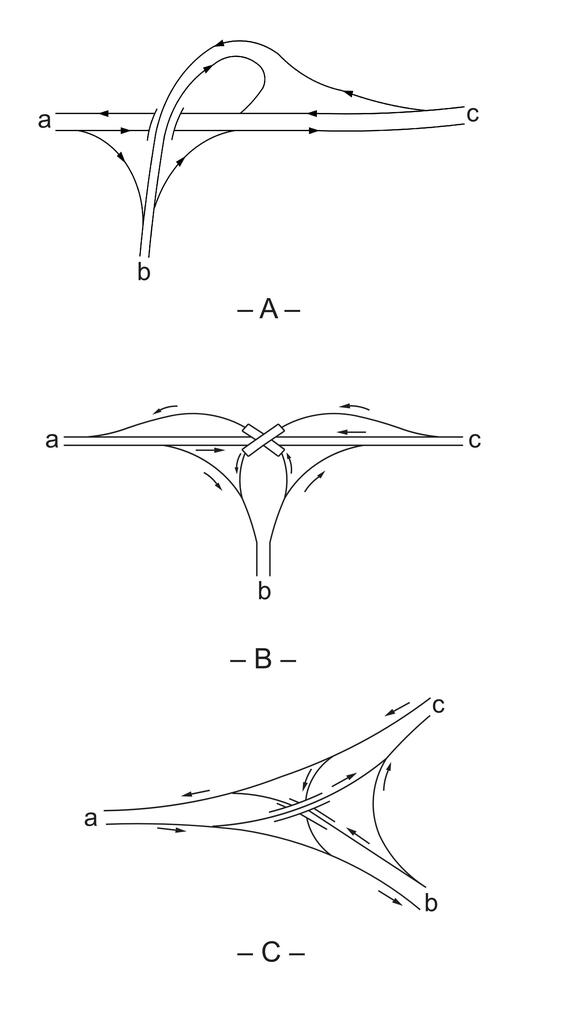
Source: Adapted from A Policy on Geometric Design of Highways and Streets, AASHTO, 2018. Chapter 10 Grade Separations and Interchanges, Figure 10-9, 10-10
Diamond Interchanges
Diamond interchanges use one-way diagonal ramps in each quadrant with two at-grade intersections provided on the minor road. If these two intersections can be properly designed, the diamond is usually the best choice of interchange where the intersecting road is not access controlled. Where topography permits, the preferred design is to elevate the minor road over the major roadway. This aids in deceleration to the lower speed roadway and in acceleration to the higher speed roadway. The advantages of diamond interchanges include:
- Continuity of pedestrian and bicycle accommodation on the minor road is easier to maintain since merging and diverging movements can be avoided
- Relatively little right-of-way is required
- The configuration allows modifications to provide greater ramp capacity, if needed in the future;
- Their common usage has resulted in a high degree of driver familiarity
- All traffic can enter and exit the freeway mainline at relatively high speeds and all exits from the freeway mainline are made before reaching the structure
- Adequate sight distance can usually be provided, and the traffic maneuvers are normally uncomplicated
- Left-turning maneuvers require little extra travel distance relative to the partial cloverleaf
The primary disadvantages of a diamond interchange are potential operational problems with the two closely-spaced intersections on the minor road, and the potential for wrong-way entry onto the ramps. For this reason, a median is often provided on the crossroad to facilitate proper channelization. Additional signing is also recommended to help prevent improper use of the ramps. Figure 7‑2 illustrates a schematic of a typical diamond interchange.
Compressed Diamond Interchanges
Compressed diamond interchanges are diamond interchanges where the nearest ramp terminal is less than 200 feet from the bridge. These interchanges are often used where right of way is restricted. Adequate sight distance based on unsignalized intersection criteria must be provided even if signals are installed. See Chapter 3 for further discussion of intersection sight distance. For further examples of design considerations, see the AASHTO Green Book.
Roundabout Interchanges
Roundabout interchanges are diamond or partial cloverleaf style interchanges with roundabouts at one or more crossroad ramp terminus. All through and turning movements on the cross street and ramps are provided by using single-lane or multilane roundabouts. The design provides a narrower bridge (no storage turn lanes) and the elimination of signal control at the interchange. Consideration needs to be given to the cross-street traffic volumes and freeway ramp volumes when analyzing the roundabout operations. Bicycle and pedestrian accommodation should be addressed taking into account the crossing locations and single-lane or multilane roundabouts. As with any form of interchange, grades should be taken into consideration. Designers should refer to Chapter 6 and the MassDOT MassDOT Guidelines for the Planning and Design of Roundabouts for additional guidance on roundabouts.
Single Point Urban Interchange (SPUI)
The SPUI interchange (also known as an urban interchange or single-point diamond interchange) consolidates left-turn movements to and from entrance and exit ramps at a single intersection as illustrated in Figure 7‑3. The primary features of a SPUI are that all four left-turning moves are controlled by a single multi-phase traffic signal system and opposing left turns operate to the left of each other. These features can allow the SPUI to significantly increase the interchange capacity. The advantages of a SPUI include:
- Vehicles making opposing left turns pass to the left of each other rather than to the right, so their paths do not intersect. In addition, the right-turn movements are typically free-flow movements and only the left turns must pass through the signalized intersection. This operation eliminates a major source of traffic conflict, thereby increasing overall intersection efficiency and reducing the traffic signal need to a three-phase operation rather than a four-phase typical of a compressed diamond interchange.
- Since the SPUI has only one intersection, as opposed to two intersections in a conventional diamond interchanges, the operation of a single traffic signal on the crossroad may result in reduced delay through the intersection area.
- Curve radii for left-turn movements through the intersection are significantly flatter than at conventional intersections, and, therefore, the left turns move at a higher speed and discharge more efficiently.
- The configuration can help to reduce left-turning lane storage problems for drivers trying to enter the freeway.
- U-turns can be easily provided for the major roadway within the ramp system.
The primary disadvantages are its higher costs because of the need for a larger structure, the need for a careful design of channelization to minimize driver confusion and the likelihood of wrong-way maneuvers, and the need for careful design of signal timing to accommodate pedestrians and bicyclists. Also, SPUIs built with a skewed angle between two roadways increase clear distances and adversely affect sight distance.
Bicycle accommodation must consider signal timing for slower cyclists. Pedestrian crossing of the cross street at ramp terminals typically adds a signal phase, resulting in reduced operational efficiency for motor vehicles. Special consideration should be given to the location and alignment of crosswalks to ensure adequate sight distance, minimize the length of the crossing, maximize vehicular storage lengths, and to coincide with driver expectations.
For further discussion, examples and design considerations see the AASHTO Green Book.
Figure 7-2: Typical Diamond Interchange (Schematic)
Source: A Policy on Geometric Design of Highways and Streets, AASHTO, 2018. Chapter 10 Grade Separations and Interchanges, Figure 10-17
Figure 7-3: Single Point Urban Interchange
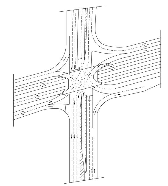
Source: A Policy on Geometric Design of Highways and Streets, AASHTO, 2018. Chapter 10 Grade Separations and Interchanges, Figure 10-24
Cloverleafs
Cloverleaf interchanges are used at four-leg intersections and combine the use of one-way diagonal ramps with loop ramps to accommodate left turn movements. Interchanges with loops in all four quadrants are referred to as full cloverleafs and all others are referred to as partial cloverleafs.
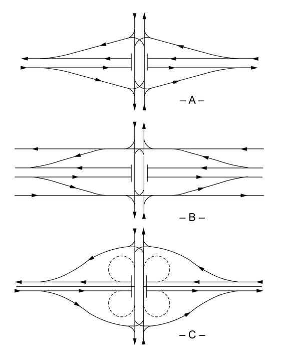
Where two access-controlled highways intersect, a full cloverleaf is the minimum type design interchange that provides connectivity for all movements between the highways. However, these interchanges introduce several undesirable operational features such as double exits and entrances from the mainline, weaving between entering and exiting vehicles, lengthy travel time and distance for left-turning vehicles, and large amounts of required right-of-way. Therefore, at system interchanges, a collector-distributor (C-D) road is often used to remove the weave from the mainline traffic. Figure 7-4 provides typical examples of full cloverleafs with and without C-D roads.
Figure 7-4: Full Cloverleafs

Source: A Policy on Geometric Design of Highways and Streets, AASHTO, 2018. Chapter 10 Grade Separations and Interchanges, Figure 10-57
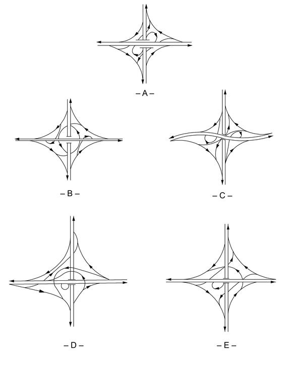
Partial cloverleafs are often used where right-of-way, multi-modal, or environmental restrictions preclude ramps in one or more quadrants. Figure 7‑5 illustrates eight examples of partial cloverleafs. In "A" and "B," both left-turn movements onto the major road are provided by loops, which is desirable. The other examples (C-F) illustrate two loops in opposite quadrants and loops in three quadrants. In these examples, the desirable feature is that no left-turn movements are made onto the major road.
Partial cloverleaf arrangements are generally used when an obstruction prevents construction of ramps in one or more quadrants, or to provide connections for all movements without intersection delays (other than those associated with merging and weaving at a full cloverleaf interchange). For freeway connections with other arterials, collectors and local roads, diamond interchanges are often preferred as discussed in "Interchange Selection Factors.”
Figure 7-5: Partial Cloverleaf Arrangements
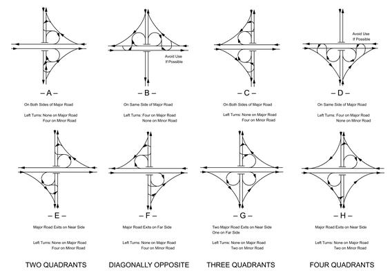
Source: A Policy on Geometric Design of Highways and Streets, AASHTO, 2018. Chapter 10 Grade Separations and Interchanges, Figure 10-30
Diverging Diamond Interchanges
The Diverging Diamond Interchange (DDI), also known as the Double Crossover Diamond (DCD), is a variation of a conventional diamond interchange. The first DDI in the United States was constructed and opened to traffic in 2009 as a retrofit of an existing conventional diamond interchange. The DDI uses directional crossover intersections to shift traffic on the cross street to the left-hand side between the ramp terminals within the interchange. Crossing the through movements to the opposite side replaces left-turn conflicts with same-direction merge/diverge movements and eliminates the need for exclusive left-turn signal phases to and from the ramp terminals. All connections from the ramps to and from the cross street are joined outside of the cross-over intersections, and these connections can be controlled by two-phase signals, have stop or yield control or be free flowing.
The DDI offers several advantages in comparison to a conventional diamond interchange. By allowing the ramp-terminal intersections to operate with simple, two-phase signal operations, the design provides flexibility to accommodate varying traffic patterns. The DDI design has significantly fewer vehicle-to-vehicle, vehicle-to-pedestrian, and vehicle-to-bike conflict points compared to a conventional diamond interchange. Left-turn volume capacity at a DDI is generally higher, and fewer and shorter signal phases are needed to accommodate both motorized and nonmotorized movements. Overall operations of a DDI may be greater compared to a conventional signalized diamond interchange due to shorter cycle lengths, reduced time lost per cycle phase, reduced stops and delay, and shorter queue lengths. The DDI also reduces the number and severity of conflict points for both motorized and nonmotorized users. The crossing distances for pedestrians are comparatively shorter, and usually involve traffic approaching from only one direction at a time. The cross-sectional characteristics of a DDI provide multiple options for facilitating convenient pedestrian and bicycle movements, and the geometry of the crossover intersections have an added benefit of reducing motorized vehicle speeds through the interchange, resulting in a traffic calming effect which may reduce crashes.
At an existing conventional diamond interchange where additional capacity is needed, it may be advantageous to convert the interchange into a DDI. Retrofitting to a DDI may be less costly than options involving widening the crossroad near the interchange (including widening the bridge) and adding additional lanes to the ramps. For new interchanges, the operational efficiency of a DDI may allow for a smaller structural footprint since fewer lanes are generally needed to accommodate the traffic demands. In some contexts, the DDI may allow for reduced right-of-way needs and construction costs compared to other interchange forms.
Figure 7-6: Diverging Diamond Interchange
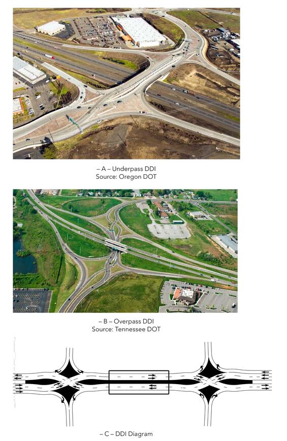
Source: A Policy on Geometric Design of Highways and Streets, AASHTO, 2018. Chapter 10 Grade Separations and Interchanges, Figure 10-27
Since the crossover area of a DDI tends to operate best at lower speeds, design speeds for crossover alignments should in the range of 20 to 35 mph [30 to 60 km/h], resulting in crossover radii in the range of 100 to 500 ft [30 to 150 m] depending upon chosen cross slope (which is typically in the range of plus or minus 2 percent).
In addition to selecting appropriate combinations of crossover radii for the reversing curves and the tangent length between them, the crossover angle is a design element that needs consideration of the trade-offs involved. The crossover angle is the acute angle between lanes between lanes of opposing traffic within the crossover based on the tangent sections or lines perpendicular to the radii at points of reverse curvature. The greater the crossover angle, the more the crossover will appear like a “normal” intersection of two different cross routes and decrease the likelihood of a driver making a wrong-way movement. The crossover angle of a DDI is generally between 30 to 50 degrees. Crossover angle less than 30 degrees may increase the potential for wrong-way movements. Additional features, such as supplemental signs and pavement markings, should be used at a DDI to minimize the likelihood of a wrong-way movement.
Directional and Semi-Directional
Direct and semi-direct connections are used for important turning movements to reduce travel distance, increase speed and capacity, eliminate weaving, and to avoid the need for out-of-direction travel in driving on a loop. Higher levels of service can be realized on direct connections and, in some instances, on semi direct ramps because of relatively high speeds and the likelihood of better terminal design. The following definitions apply to directional and semi-directional interchanges:
- Direct Ramp Connection – A ramp that does not deviate greatly from the intended direction of travel (as does a loop, for example).
- Semi-Direct Ramp Connection – A ramp that is indirect in alignment yet more direct than loops.
- Directional Interchange – An interchange where one or more left turning movements are provided by direct connection, even if the minor left-turn movements are accommodated on loops.
- Semi-Directional Interchange – An interchange where one or more left turning movements are provided by semi-direct connections, even if the minor left-turn movements are accommodated on loops.
- Fully Directional Interchange – An interchange where all left-turning movements are provided by direct connections. Fully directional interchanges are generally preferred where two high-volume freeways intersect. While fully directional interchanges can be costly to construct due to an increased number of bridge crossings, they offer high-capacity movements for both through and turning traffic with comparatively little additional area needed for construction.
Direct or semi-direct connections are used for heavy left-turn movements to reduce travel distance, increase speed and capacity, and eliminate weaving. Examples of direct and semi-direct interchanges are shown in Figures 7-7, 7-8 and 7-9.
For further variations and examples of interchange types and related design considerations see the AASHTO Green Book.
Figure 7-7: Semidirect Interchanges with Weaving
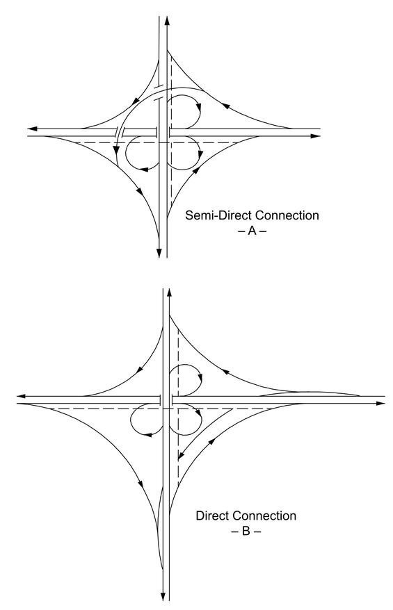
Source: A Policy on Geometric Design of Highways and Streets, AASHTO, 2018. Chapter 10 Grade Separations and Interchanges, Figure 10-33
Figure 7-8: Semidirect Interchanges without Weaving
Source: A Policy on Geometric Design of Highways and Streets, AASHTO, 2018. Chapter 10 Grade Separations and Interchanges, Figure 10-34
Figure 7-9: Semidirect and Directional Interchanges – Multilevel Structures
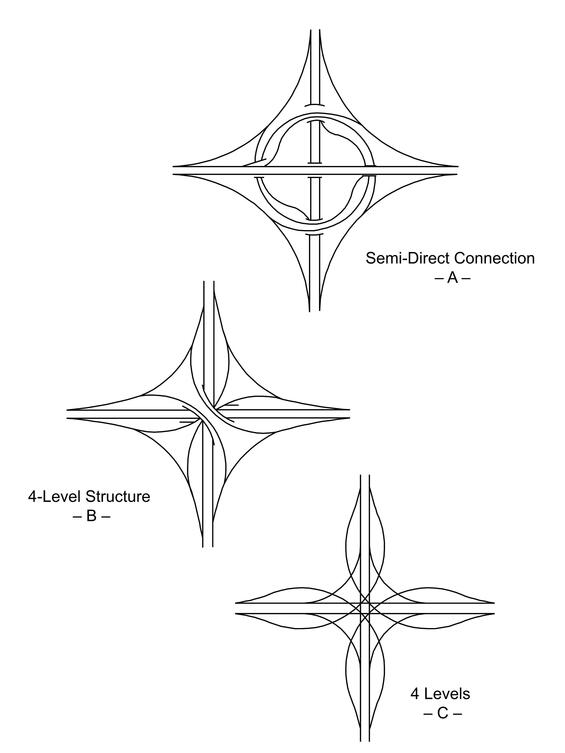
Source: A Policy on Geometric Design of Highways and Streets, AASHTO, 2018. Chapter 10 Grade Separations and Interchanges, Figure 10-35
7.4 General Design Considerations
Interchanges are expensive, and it is therefore often necessary to develop and study the feasibility of several alternatives in depth, as described in Chapter 2. Interchanges must also meet the policies set forth by the FHWA and described in the “Interchange Justification/Modification Reports” section.
Interchange Type Selection
Once several alternative interchange designs have been developed, they should be evaluated for application to the location under consideration based on the following two key considerations:
- Context: In rural areas where interchanges are relatively infrequent, the design is often selected primarily based on consistency (driver expectation) and environmental constraints in the interchange area. In urban areas, where restricted right-of-way and closer spacing of interchanges are common, the design of the interchange may be severely constrained. A collector distributor road may be necessary between closely-spaced interchanges. The operational characteristics of the intersecting road and nearby interchanges will also be heavily influence the design of an interchange.
- Accessibility: Ideally, interchanges should provide for all movements, even when the anticipated turning volume is low. An omitted maneuver causes confusion to those drivers searching for the exit or entrance. Particular attention to signing must be made to minimize confusion. In addition, unanticipated future developments may increase the demand for a given maneuver. Even when all ramps are not constructed, sufficient right-of-way should be acquired for completing the interchange later.
Additionally, interchange design should account for the following transportation system considerations:
- Compatibility with the surrounding highway system.
- Road user impacts (safety, travel distance and time, convenience, and comfort for all users, including pedestrians and bicyclists).
- Right-of-way impacts and availability.
- Uniformity of exit and entrance patterns.
- Operational characteristics (single versus double exits, weaving, signing).
- Construction and maintenance costs.
Figure 7-10 depicts typical interchange configurations related to classifications of intersecting facilities in rural, suburban, and urban environments.
For system interchanges, directional and semi-directional interchanges are preferred over cloverleaf designs from a user safety and operational efficiency perspective. However, many existing freeways were previously constructed using cloverleaf interchange configurations, and projects to modify these existing interchanges are common.
At service interchanges, the choice of interchange is usually between a diamond and cloverleaf configuration. Designers should consider the following when making the selection:
- Unlike diamond interchanges and partial cloverleafs, full cloverleafs do not employ 90-degree intersections. Pedestrian and bicycle movements along cross streets are more difficult to accommodate safely at full cloverleaf interchanges than at partial cloverleaf or diamond interchanges because vehicular movements are usually free-flow.
- All freeway exit maneuvers at diamond interchanges are executed before reaching the structure, conforming to driver expectations. Diamond interchanges also eliminate weaving on the freeway mainline and cross street. Some partial cloverleaf options can also provide these advantages.
- Partial cloverleafs may be suitable for locations where ramp construction in one or more quadrants of the interchange is infeasible or undesirable. Partial cloverleafs with loops in opposite quadrants are very desirable because they eliminate the weaving problem associated with full cloverleaf designs.
- The double exit/entrance at cloverleafs can result in signing problems and driver confusion. Collector-distributor roads are often recommended to address signage problems and reduce weaving on the freeway mainline.
- Ramps at diamond interchanges can be widened to increase storage capacity. Loop ramps, regardless of width, almost always operate as a single lane, thereby limiting storage capacity. Operational capacity needs to consider the control at the ramp terminal and may not always be significantly greater than with free-flow loops.
- The loops in cloverleafs result in a greater travel distance for left-turning vehicles than diamonds. Loops operate at lower speeds, especially for trucks, which have the potential to turn over if traveling the loop too fast.
- Cloverleafs require more right-of-way and are more expensive to construct than diamonds.
- Full cloverleafs provide higher capacity than most diamond configurations, since movements at the ramp terminals are usually free-flow and subject only to weaving and merging delays rather intersection control delay.
Full cloverleaf interchanges are often considered more appropriate than diamonds when traffic volumes are high. However, when compared with the advantages of diamonds in terms of pedestrian and bicycle accommodation, right-of-way requirements, and driver expectations, the designer should investigate measures to increase the capacity of diamond interchanges, such as advanced signal phasing, signal coordination on the minor road, roundabout intersections, or SPUI interchanges before selecting a cloverleaf design.
Figure 7-10: Interchanges on Freeways as Related to Types of Intersecting Facilities and Surrounding Area
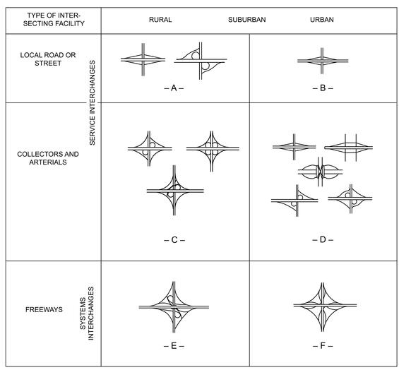
Source: A Policy on Geometric Design of Highways and Streets, AASHTO, 2018. Chapter 10 Grade Separations and Interchanges, Figure 10-45
Capacity and Level of Service (LOS)
An interchange must be designed to accommodate the anticipated activity levels for the design year (see Chapter 3 for details). The capacity and level of service (LOS) for an interchange will depend on the operation of its individual elements along with the interaction and coordination of each of these elements in the overall design. The individual elements are as follows:
- Basic freeway section where interchanges are not present
- Freeway/ramp junctions or terminals
- Weaving areas
- Ramps
- Ramp/minor road intersections
For most situations, the capacity and LOS at interchanges is focused on motor vehicles since interchanges are most often used at freeway connection points.
The basic reference for LOS measures for interchanges is the Highway Capacity Manual. It is desirable for the LOS of each interchange element to be at least that provided on the basic freeway section. In addition, the designer should ensure that the operation of the ramp/minor road intersection will not impair the operation of the mainline. This will likely involve considering the operational characteristics on the minor road for some distance in either direction from the interchange.
Safety Considerations
Typical design challenges at interchanges include:
- Sight Distance at Exit Points: Sight distance is often determined with respect to the gore, which is the area where a ramp diverges from the mainline. When feasible, decision sight distance should be provided to enable drivers approaching freeway exits to see the pavement surface from the painted gore nose to the limit of the paved gore. Proper advance signing of exits is also essential, and additional signing is required when it is not possible to obtain the decision sight distance.
- Exit Speed Changes: The design should provide enough distance to allow for safe deceleration from the freeway design speed to the design speed of the first exit curve.
- Merges: The most frequent crash type at interchanges is the rear-end collision at entrances onto the freeway. This problem can be reduced by providing an acceleration lane of sufficient length with adequate sight distance to allow a merging vehicle to attain speed and find a sufficient gap into which to merge.
- Left-Side Entrances and Exits: Left-side entrances and exits should be avoided, as they are contrary to driver expectations and have been associated with higher crash rates.
- Fixed-Object Hazards: A number of fixed objects may be located within interchanges, such as signs at exit gores or bridge piers and rails. These should be removed where possible, placed outside of the recovery area where possible, made breakaway, or shielded with barriers or impact attenuators.
- Wrong-Way Entrances: In almost all cases, wrong-way maneuvers originate at interchanges. Some cannot be avoided, but others may result from driver confusion due to poor visibility, deceptive ramp arrangement, or inadequate signing. The interchange design must attempt to minimize wrong-way possibilities. This includes staggering ramp terminals and controlling access in the vicinity of the ramps.
- Excessive Speed on Minor Roadways: Ramp and merge designs should slow drivers leaving the high-speed roadway so that they will not exceed the design speed on the secondary road. The section of the secondary road in the interchange area should have a design speed similar to (not faster than) the design of adjoining sections of that road.
7.5 Traffic Lane Principles
A variety of traffic lane principles are important when designing an interchange. Applying these principles helps minimize confusion, operational problems, and the number of crashes.
Basic Number of Lanes
Designating the basic number of lanes is fundamental to establishing the number and arrangement of lanes on a freeway. Designers should maintain a consistent number of lanes along any route of arterial character. Thus, the basic number of lanes is defined as a minimum number of lanes designated and maintained over a significant length of a route, irrespective of changes in traffic volumes and lane-balance needs.
The number of lanes should remain constant over short distances. For example, a lane should not be dropped at the exit of a diamond interchange and then added at the downstream entrance simply because traffic volumes between the exit and entrance drop significantly. In other words, a basic lane between closely-spaced interchanges should not be dropped in that short section of highway if the estimated traffic volume does not warrant the higher number of lanes, if the lane will be added back just after the interchanges.
As illustrated in Figure 7‑11, the basic number of lanes on freeways is maintained over significant lengths of the routes, as A to B or C to D. The number of lanes is predicated on the general volume level of traffic over a substantial length of the facility. The volume considered here is the DHV (normally, representative of the morning or evening or evening weekday peak.)
Localized variations are ignored, so short sections of roadway that carry lower volumes would theoretically have reserve capacity, and short sections of roadway carrying somewhat higher volumes would be augmented by the addition of auxiliary lanes within these sections.
An increase in the basic number of lanes is needed where traffic volume builds up sufficiently over a substantial length of the facility.
The basic number of lanes may be decreased where traffic volumes are significantly reduced for a substantial length of the facility. Lane reductions are discussed in the section on Freeway Lane Drops.
Figure 7-11: Schematic of Basic Number of Lanes
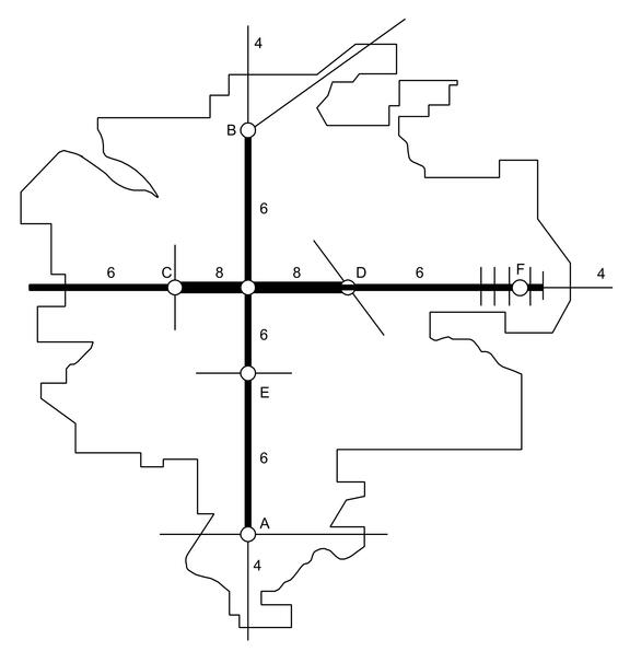
Source: A Policy on Geometric Design of Highways and Streets, AASHTO, 2018. Chapter 10 Grade Separations and Interchanges, Figure 10-51
Freeway Lane Drops
Freeway lane drops, where the basic number of lanes is decreased, must be carefully designed. They should occur on the freeway mainline away from any other activity, such as interchange exits and entrances. Designers should consider the following recommendations when designing a freeway lane drop:
- Location: The lane drop should occur approximately 2,000-to-3,000 ft beyond the previous interchange. This distance allows adequate signing and adjustments from the interchange without being so far downstream that drivers become accustomed to the number of lanes and are surprised by the lane drop. In addition, a lane should not be dropped on a horizontal curve or where other signing is required, such as for an upcoming exit.
- Sight Distance: The lane drop should be located so that the surface of the roadway within the transition remains visible for its entire distance. This favors, for example, placing a lane drop within a sag vertical curve rather than just beyond a crest. Decision sight distance to the roadway surface is desirable. (For information on Decision Sight Distance see Chapter 3).
- Transition: The desirable taper rate is 70:1 for the transition at the lane drop. The minimum is 50:1.
- Right-Side Versus Left-Side Drop: All freeway lane drops should be on the right side unless specific site conditions greatly favor a left-side lane reduction.
- Signing: Motorists must be warned and guided into the lane reduction. Advance signing and pavement markings must conform to the requirements of the Manual on Uniform Traffic Control Devices (MUTCD).
Lane Balance
Lane balance is a design principle involving the proper arrangement of traffic lanes on the freeway and ramps. To realize efficient traffic operation through and beyond an interchange, designers should balance the number of traffic lanes on the freeway with the number of ramps. Design traffic volumes and a capacity analysis determine the basic number of lanes to be used on the highway and the minimum number of lanes on the ramps. After the basic number of lanes is determined for each roadway, the balance in the number of lanes should be checked on the basis of the following principles:
- At entrances, the number of lanes beyond the merging of two traffic streams should not be less than the sum of all traffic lanes on the merging roadways, minus one, but may be equal to the sum of all traffic lanes on the merging highway.
- At exits, the number of approach lanes on the highway must be equal to the number of lanes on the highway beyond the exit plus the number of lanes on the exit, minus one. An exception to this principle would be at cloverleaf loop ramp exits, which follow the loop ramp entrance, or at exits between closely-spaced interchanges (i.e., interchanges where the distance between the end of the taper of the entrance terminal and the beginning of the taper of the exit terminal is less than 1,500 ft and a continuous auxiliary lane between the terminals is being used.) In these cases, the auxiliary lane may be dropped in a single-lane exit with the number of lanes on the approach roadway being equal to the number of through lanes beyond the exit plus the lane on the exit.
- The traveled way of the highway should be reduced by not more than one traffic lane at a time.
Figure 7‑12 illustrates the typical treatment of the four-lane freeway with a two-lane exit followed by a two-lane entrance.
Figure 7-12: Coordination of Lane Balance and Basic Number of Lanes
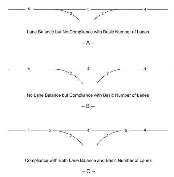
Source: A Policy on Geometric Design of Highways and Streets, AASHTO, 2018. Chapter 10 Grade Separations and Interchanges, Figure 10-53
Auxiliary Lanes
Variations in traffic demand over short distances should be accommodated by means of auxiliary lanes, where needed. Anauxiliary lane is defined as the portion of the roadway adjoining the traveled way for speed change, turning, storage for turning, weaving, truck climbing, and other purposes supplementary to through-traffic movement. The width of an auxiliary lane should equal that of the through lanes. An auxiliary lane may be provided to comply with the concept of lane balance; to comply with capacity requirements in the case of adverse grades; or to accommodate speed changes, weaving, and maneuvering of entering and exiting traffic. Where auxiliary lanes are provided along freeway main lanes, the adjacent shoulder would desirably be 8-to-12 ft in width, with a minimum of 6 ft.
Auxiliary lanes may be added to satisfy capacity and weaving requirements between interchanges, to accommodate traffic pattern variations at interchanges, and to simplify operations (such as reducing lane changing). Designers must always apply the principles of lane balance when designing auxiliary lanes so that the necessary balance between traffic load and capacity is provided, and lane balance and needed operational flexibility are realized.
Designers can improve operational efficiency by using a continuous auxiliary lane between the entrance and exit terminals where interchanges are closely spaced, the distance between the end of the taper on the entrance terminal and the beginning of the taper on the exit terminal is short, and/or where local frontage roads do not exist.
Where interchanges are closely spaced in urban areas, the acceleration lane from an entrance ramp should be extended to the deceleration lane of a downstream exit ramp. Figure 7‑13 shows alternatives for dropping auxiliary lanes.
Figure 7-13: Alternatives in Dropping Auxiliary Lanes
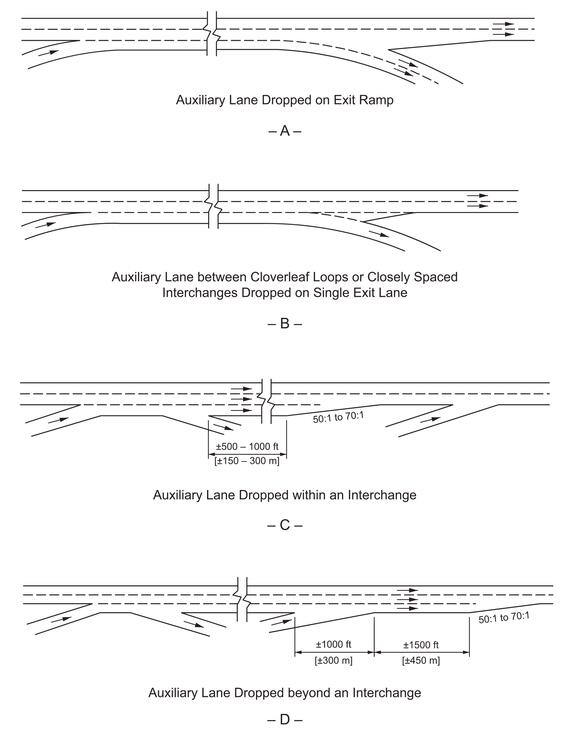
Source: A Policy on Geometric Design of Highways and Streets, AASHTO, 2018. Chapter 10 Grade Separations and Interchanges, Figure 10-54
Distance Between Successive Ramp Terminals
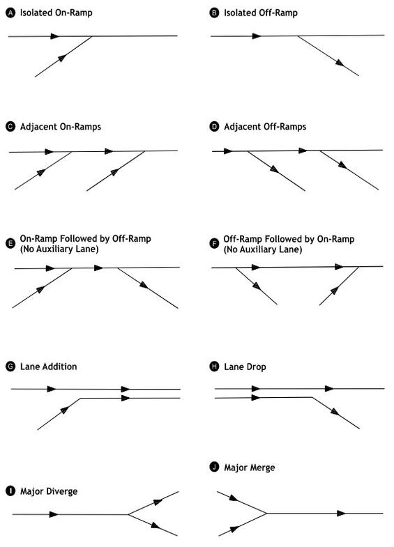
On freeways, there are frequently two or more ramp terminals in close succession along the through lanes. To provide sufficient maneuvering length and adequate space for signing, there must be a reasonable distance between terminals. Spacing between successive outer ramp terminals depends on the classification of the interchanges involved, the function of the ramp pairs (entrance (EN) or exit (EX)), and weaving potential, when applicable. The five possible ramp-pair combinations are:
- Entrance followed by entrance (EN-EN).
- Exit followed by exit (EX-EX).
- Exit followed by entrance (EX-EN).
- Entrance followed by exit (EN-EX) (weaving).
- Turning roadways.
When an entrance ramp is followed by an exit ramp, the absolute minimum distance between the successive noses is governed by weaving consideration. Weaving sections are highway segments where the pattern of traffic entering and leaving at contiguous points of access results in vehicle paths crossing each other (see the Highway Capacity Manual for capacity of weaving sections and Chapter 2 of the AASHTO Green Book for weaving lengths and widths.)
Figure 7‑14 shows the various ramp-pair combinations, with the length between successive ramp terminals labeled as “L”.
Table 7-1 contains minimum values for spacing ramp terminals for the various ramp-pair combinations as they are applicable to the interchange classifications. Distance between successive ramp terminals should be determined by the weaving lengths.
Figure 7-14: Ramp-Pair Combinations

Source: A Policy on Geometric Design of Highways and Streets, AASHTO, 2018. Chapter 10 Grade Separations and Interchanges, Figure 10-70
Table 7-1: Recommended Minimum Ramp Terminal Spacing
| Ramp-Pair Combination | Roadway or Interchange Type | Minimum Lengths Measured Between Successive Ramp Terminals (ft) |
|---|---|---|
| EN-EN or EX-EX | Full freeway | 1000 |
| EN-EN or EX-EX | Collector distributor road | 800 |
| EX-EN | Full freeway | 500 |
| EX-EN | Collector distributor road | 400 |
| Turning Roadways | System interchange | 800 |
| Turning Roadways | Service interchange | 600 |
| EN-EX (Weaving) | Full freeway - System to service interchange | 2000 |
| EN-EX (Weaving) | Collector distributor road - System to service interchange | 1600 |
| EN-EX (Weaving) | Full freeway - Service to service interchange | 1600 |
| EN-EX (Weaving) | Collector distributor road - Service to service interchange | 1000 |
Note: EN = Entrance; EX = Exit
Source: A Policy on Geometric Design of Highways and Streets, AASHTO, 2018. Chapter 10 Grade Separations and Interchanges, Figure 10-70
A notable exception to this length policy for EN-EX ramp combinations is the distance between loop ramps of cloverleaf interchanges. For these interchanges, the distance between EN-EX ramp noses primarily depends on loop ramp radii and roadway and median widths. A recovery lane beyond the nose of the loop ramp exit is desirable.
When the distance between the successive noses is less than 1,500 ft, the speed-change lanes should be connected to provide an auxiliary lane. This auxiliary lane is provided for improved traffic operation over relatively short sections of the freeway route and is not considered as an addition to the basic number of lanes. See the AASHTOGreen Book for additional information on auxiliary lane design and lane balance criteria at interchanges.
Approaches to Interchanges
Traffic passing through an interchange should be provided with the same level of safety and convenience as that given on the approaching highway. Highway elements, including design speed, alignment, profile, and cross-sectional elements, should be consistent with those on the approaching highways. The following considerations are applicable when designing highway approaches to structures:
- Through interchange areas, changes in alignment, and cross-sectional elements may be needed to ensure proper operation and to develop the capacity needed at the ramp terminals.
- Pedestrian and bicycle accommodation that is consistent with the remaining segments of the roadway should continue through interchange area.
- Relatively sharp horizontal or vertical curves should be avoided.
- Four-lane roadways should be divided through interchange areas.
7.6 Freeway/Ramp Junctions
This section discusses the two basic types of freeway/ramp junctions, exits and entrances (often encountered in this order when traveling on the freeway mainline), as well as weaving areas, major forks, and branch connections.
Exit Ramps
Exit ramps are one-way roadways that allow traffic to exit the freeway, and they provide access to other crossing highways. The following design considerations apply to exit ramps.
Sight Distance
Sight distance is the length of roadway visible to a driver. Decision sight distance (see Chapter 3) should be provided for drivers approaching an exit. Sufficient sight distance is particularly important for exit loops immediately beyond a structure. Vertical curvature or bridge piers can obstruct the exit point if not carefully designed. When measuring for adequate sight distance, the designer should use the pavement surface at the gore nose as height of object.
Deceleration Lanes
Deceleration lanes allow traffic exiting a major street to slow down to a speed safe enough to make a left or right turn at an intersection without affecting the main flow of traffic. Sufficient deceleration distance is needed to allow an existing vehicle to leave the freeway mainline safely and comfortably. All deceleration should occur within the full width of the deceleration lane. The length of the deceleration lane will depend on the design speed of the mainline and the design speed of the first (or controlling) curve on the exit ramp. In addition, if compound curvature is used, there should be sufficient deceleration in advance of each successively sharper curve.
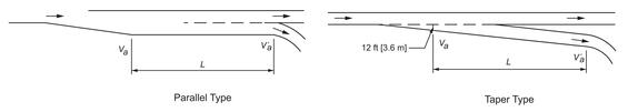
Table 7‑2 provides the deceleration distance for various combinations of highway design speeds and exit curve design speeds and Figure 7‑15 shows diagrams for parallel and taper type exit terminals using these values. Figure 7‑28, Figure 7‑29, and Figure 7‑30 at the end of this chapter illustrate the standard MassDOT designs for freeway exits at interchanges. Deceleration lanes can be the taper-type or the parallel-type, with the parallel-type preferred. It is necessary for a full deceleration lane to be developed and visibly marked well ahead of the gore area.
Table 7-2: Minimum Deceleration Lengths for Exit Terminals with Flat Grades of 3% or Less
| Highway Design Speed (mph) | V' = Stop Condition (V'a = 0) | V' = 15 (V'a = 14) | V' = 20 (V'a = 18) | V' = 25 (V'a = 22) | V' = 30 (V'a = 26 | V' = 35 (V'a = 30) | V' = 40 (V'a = 36) | V' = 45 (V'a = 40) | V' = 50 (V'a = 44) |
|---|---|---|---|---|---|---|---|---|---|
| 30 (Va = 28) | 235 | 200 | 170 | 140 | - | - | - | - | - |
| 35 (Va = 32) | 280 | 50 | 210 | 185 | 150 | - | - | - | - |
| 40 (Va = 36) | 320 | 295 | 265 | 235 | 185 | 155 | - | - | - |
| 45 (Va = 40) | 385 | 350 | 325 | 295 | 250 | 220 | - | - | - |
| 50 (Va = 44) | 435 | 405 | 385 | 355 | 315 | 285 | 225 | 175 | - |
| 55 (Va = 48) | 480 | 455 | 440 | 410 | 380 | 350 | 285 | 235 | - |
| 60 (Va = 52) | 530 | 500 | 480 | 460 | 430 | 405 | 350 | 300 | 240 |
| 65 (Va = 55) | 570 | 540 | 520 | 500 | 470 | 440 | 390 | 340 | 280 |
| 70 (Va = 58) | 615 | 590 | 570 | 550 | 520 | 490 | 440 | 390 | 340 |
| 75 (Va = 61) | 660 | 635 | 620 | 600 | 575 | 535 | 490 | 440 | 390 |
Va = Average running speed on highway (i.e., diverge speed) (mph)
V' = Design speed of controlling feature on ramp (mph)
V'a = Average running speed at controlling feature on ramp (mph)
Source: A Policy on Geometric Design of Highways and Streets, AASHTO, 2018. Chapter 10 Grade Separations and Interchanges, Table 10-6
Figure 7-15: Deceleration Lengths for Parallel and Taper Type Exit Terminals with Flat Grades of 3% or Less
Source: A Policy on Geometric Design of Highways and Streets, AASHTO, 2018. Chapter 10 Grade Separations and Interchanges, Table 10-6
Va = Average running speed on highway (i.e. diverge speed) (mph)
V’a = Average running speed at controlling feature on ramp (mph)
La = Deceleration lane length (ft)
Deceleration lanes are measured from the point where the lane reaches 12-ft-wide to the painted nose for parallel-type and the first controlling curve for taper-type ramps. Greater distances should be provided if practical. If the deceleration lane is on a grade of 3 percent or more, the length of the lane should be adjusted according to the criteria in Table 7‑4.
Superelevation
Superelevation is the banking of a roadway along a horizontal curve so motorists can safely and comfortably maneuver the curve at reasonable speeds. The superelevation at an exit ramp must be developed to transition the driver properly from the mainline to the curvature at the exit. The principles of superelevation for open highways, as discussed in Chapter 4, should be applied to the exit design with the following criteria applied:
- The maximum superelevation rate in Massachusetts is 6.0 percent.
- Preferably, full superelevation is achieved at the PCC at the gore nose. However, this is subject to the minimum longitudinal slopes described in Chapter 4.
- The paved portion of the gore is normally sloped at 3.0 percent.
Gore Area
Thegore area is normally considered to be both the paved triangular area between the through lane and the exit lane and the unpaved graded area that extends downstream beyond the gore nose. Designers should consider the following when designing the gore:
- Signing in advance of the exit and at the divergence should be in accordance with the MUTCD. This also applies to the pavement markings in the triangular area upstream from the gore nose.
- If possible, the area beyond the gore nose should be free of signs and luminaire supports. If they must be present, they must be yielding/breakaway or shielded by guardrail or impact attenuators.
- The graded area beyond the gore nose should be as flat as possible. If the difference in elevation between the exit ramp or loop and the mainline increases rapidly, this may not be possible. These areas will likely be non-traversable, and the gore design must shield these areas from the driver. Often, the vertical divergence of the ramp and mainline will warrant protection for both roadways beyond the gore.
Entrance Ramps
Entrance ramps are one-way roadways that allow traffic to enter a freeway. Design considerations for entrance ramps are described below.
Sight Distance
Decision sight distance should be provided for drivers on the entrance ramp and on the mainline approaching an entrance terminal. Drivers on the mainline need sufficient distance to see the merging traffic so that they can adjust their speed or change lanes to allow the merging traffic to enter the freeway. Likewise, drivers on the entrance ramp need to see a sufficient distance upstream from the entrance to locate the gaps in the traffic stream within which to merge. When measuring decision sight distance for entrance ramps, use 3.5 ft as the height-of-eye and objects.
Acceleration Lanes
A properly designed acceleration lane will facilitate driver comfort, traffic operations, and safety.
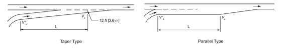
Figure 7‑31, Figure 7‑32, and Figure 7‑33 at the end of this chapter illustrate the MassDOT standard designs for entrance ramps. The length of the acceleration lane will primarily depend on the design speed of the last (or controlling) curve on the entrance ramp and the design speed of the mainline.
Table 7‑3 provides data for the minimum lengths of acceleration lanes. These lengths are for the full width of the acceleration lane and are measured from the end of the painted nose for parallel-type, and from the end of the last controlling curve on taper-type ramp junctions, to a point where the full 12-ft lane width terminates. Taper lengths, typically 300 ft, are in addition to the acceleration lane lengths. If the acceleration lane is on a grade of 3 percent or more, the length of the lane should be adjusted according to the criteria in Table 7‑4, Table 7‑5, Table 7‑6, and Table 7-7.
The values in Table 7‑3 provide sufficient distance for vehicle acceleration; however, they may not safely allow a vehicle to merge into the mainline if traffic volumes are high. Where the mainline and ramp will carry traffic volumes approaching the design capacity of the merging area, the acceleration lane length should be extended by 200 ft or more. Figure 7‑16 shows diagrams for parallel and taper type exit terminals using these values.
Table 7-3: Minimum Acceleration Lengths for Entrance Terminals with Flat Grades of 3% or Less
| Highway Design Speed (mph)< | V' = Stop Condition (V'a = 0) | V' = 15 (V'a = 14) | V' = 20 (V'a = 18) | V' = 25 (V'a = 22) | V' = 30 (V'a = 26) | V' = 35 (V'a = 30) | V' = 40 (V'a = 36) | V' = 45 (V'a = 40) | V' = 50 (V'a = 44) |
|---|---|---|---|---|---|---|---|---|---|
| 30 (Va = 23) | 180 | 140 | - | - | - | - | - | - | - |
| 35 (Va = 27) | 280 | 220 | 160 | - | - | - | - | - | - |
| 40 (Va = 31) | 360 | 300 | 270 | 210 | 120 | - | - | - | - |
| 45 (Va = 35) | 560 | 490 | 440 | 380 | 280 | 160 | - | - | - |
| 50 (Va = 39) | 720 | 660 | 610 | 550 | 450 | 350 | 130 | - | - |
| 55 (Va = 43) | 960 | 900 | 810 | 780 | 670 | 550 | 320 | 150 | - |
| 60 (Va = 47) | 1200 | 1140 | 1100 | 1020 | 910 | 800 | 550 | 420 | 180 |
| 65 (Va = 50) | 1410td> | 1350 | 1310 | 1220 | 1120 | 1000 | 770 | 600 | 370 |
| 70 (Va = 53) | 1620 | 1560 | 1520 | 1420 | 1350 | 1230 | 1000 | 820 | 580 |
| 75 (Va = 65) | 1790 | 1730 | 1630 | 1580 | 1510 | 1420 | 1160 | 1040 | 780 |
Va = Merge speed (mph)
V' = Design speed of controlling feature on ramp (mph)
V'a = Average running speed at controlling feature on ramp (mph)
Source: A Policy on Geometric Design of Highways and Streets, AASHTO, 2018. Chapter 10 Grade Separations and Interchanges, Table 10-4
Figure 7-16: Acceleration Lengths for Parallel and Taper Type Entrance Terminals with Flat Grades of 3% or Less
Source: A Policy on Geometric Design of Highways and Streets, AASHTO, 2018. Chapter 10 Grade Separations and Interchanges, Table 10-4
Table 7-4: Deceleration Lane Ratio of Length on Grade to Length on Level by Grade for All Design Speeds
| Design Speed of Highway (mph) | Upgrade | Downgrade |
|---|---|---|
| All Speeds | 3 to 4% = 0.9 | 3 to 4% = 1.2 |
| All Speeds | 5 to 6 % = 0.8 | 5 to 6% = 1.35 |
Source: A Policy on Geometric Design of Highways and Streets, AASHTO, 2018. Chapter 10 Grade Separations and Interchanges, Table 10-5
Table 7-5: Acceleration Lane Ratio of Length on Grade to Length on Level for 3 to 4% Upgrades
| Design Speed of Highway (mph) | 20 mph Design Speed of Turning Curve | 30 mph Design Speed of Turning Curve | 40 mph Design Speed of Turning Curve | 50 mph Design Speed of Turning Curve |
|---|---|---|---|---|
| 40 | 1.3 | 1.3 | - | - |
| 45 | 1.3 | 1.35 | - | - |
| 50 | 1.3 | 1.4 | 1.4 | - |
| 55 | 1.35 | 1.45 | 1.45 | - |
| 60 | 1.4 | 1.5 | 1.5 | 1.6 |
| 65 | 1.45 | 1.55 | 1.6 | 1.7 |
| 70 | 1.5 | 1.6 | 1.7 | 1.8 |
| 75 | 1.6 | 1.7 | 1.8 | 2.0 |
Source: A Policy on Geometric Design of Highways and Streets, AASHTO, 2018. Chapter 10 Grade Separations and Interchanges, Table 10-5
Table 7-6: Acceleration Lane Ratio of Length on Grade to Length on Level for 5 to 6% Upgrades
| Design Speed of Highway (mph) | 20 mph Design Speed of Turning Curve | 30 mph Design Speed of Turning Curve | 40 mph Design Speed of Turning Curve | 50 mph Design Speed of Turning Curve |
|---|---|---|---|---|
| 40 | 1.5 | 1.5 | - | - |
| 45 | 1.5 | 1.6 | - | - |
| 50 | 1.5 | 1.7 | 1.9 | - |
| 55 | 1.6 | 1.8 | 2.05 | - |
| 60 | 1.7 | 1.9 | 2.2 | 2.5 |
| 65 | 1.85 | 2.05 | 2.4 | 2.75 |
| 70 | 2.0 | 2.2 | 2.6 | 3.0 |
| 75 | 2.15 | 2.35 | 2.8 | 3.25 |
Source: A Policy on Geometric Design of Highways and Streets, AASHTO, 2018. Chapter 10 Grade Separations and Interchanges, Table 10-5
Table 7-7: Acceleration Lane Ratio of Length on Grade to Length on Level for All Speeds
| Design Speed of Highway (mph) | -3% to -4% Grade | -5% to -6% Grade |
|---|---|---|
| 40 | 1.5 | 1.5 |
| 45 | 1.5 | 1.6 |
| 50 | 1.5 | 1.7 |
| 55 | 1.6 | 1.8 |
| 60 | 1.7 | 1.9 |
| 65 | 1.85 | 2.05 |
| 70 | 2.0 | 2.2 |
| 75 | 2.15 | 2.35 |
Source: A Policy on Geometric Design of Highways and Streets, AASHTO, 2018. Chapter 10 Grade Separations and Interchanges, Table 10-5
Superelevation
Ramp superelevation should gradually transition to meet the normal cross slope of the mainline. The principles of superelevation for open highways, as discussed in Chapter 4, should be applied to the entrance design with the following criteria:
- The maximum superelevation rate in Massachusetts is 6.0 percent.
- Preferably, the cross slope of the acceleration lane will equal the cross slope of the adjacent through lane at the PT of the flat horizontal curve near the entrance gore.
- The superelevation transition should not exceed the minimum longitudinal slopes provided in Chapter 4.
Weaving Areas
Weaving occurs where one-way traffic streams cross by merging and diverging maneuvers. This frequently occurs within an interchange or between two closely-spaced interchanges. Figure 7-17 illustrates a simple weave diagram and the length over which a weaving distance is measured.
Figure 7-17: Weaving Areas
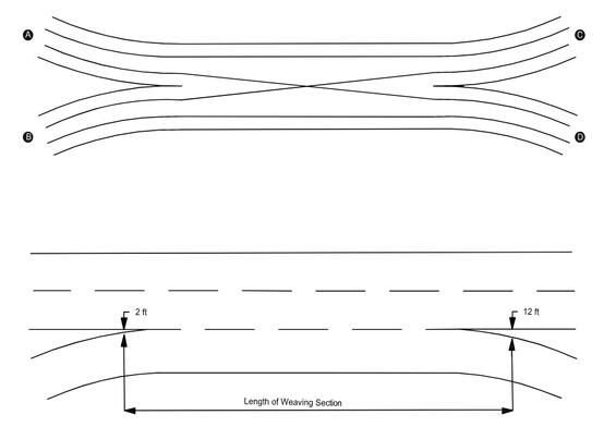
Source: Adapted from Highway Capacity Manual, TRB, 2000. Exhibits 13-7, 13-11
The capacity and LOS calculations are made from the methodology presented in the Highway Capacity Manual. The methodology determines the needed length on the weaving section to accommodate the predicted traffic conditions, including the weaving and non-weaving volumes and the average running speed of those volumes. Important elements to consider in this analysis are as follows:
- The number of lanes in the weaving areas.
- The configuration of the section in terms of lane balance (i.e., adding and dropping auxiliary lanes).
- The LOS (preferably, it will be the same as the mainline; it should not be more than one level below the mainline).
- The speed of weaving vehicles should be within 5 mph of non-weaving vehicles to provide acceptable operation.
Figure 7-15 illustrates a ramp-weave section and three major-weave sections. The ramp weave section occurs in cloverleaf interchanges where a freeway entrance from an inner loop is immediately followed by an exit onto an inner loop. The entrance and exit are joined by a continuous auxiliary lane. This weaving configuration is complicated because all weaving vehicles are involved in a ramp movement, which usually requires reduced speeds due to restrictive geometry. Therefore, three vehicle operations are occurring simultaneously — weaving, acceleration, and deceleration. Designers should use the methodology in the Highway Capacity Manual to determine the needed length for this section.
Figure 7‑34 at the end of this chapter illustrates the design details for the interior of a clover leaf interchange and provides the minimum distance between the entrance and exit loops within the interchange area. If the weave area is on a freeway, or if the site conditions will not allow the necessary distance, a collector-distributor road should be provided.
Major-weave sections differ from the ramp-weave in that multiple lanes are involved, and the geometry allows weaving speeds approximately equal to the speed on the open freeway. The Type 1 weave shown in Figure 7-15 is undesirable because of the lack of lane balance. The Highway Capacity Manual provides the methodologies for computing the length, capacity, and LOS for weaving sections.
Figure 7-18: Weaving Configuration
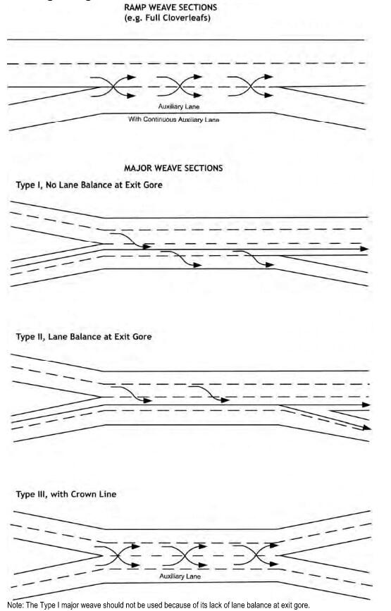
Source: Adapted from Highway Capacity Manual, TRB, 2000. Chapter 13 Freeway Concepts, Exhibits 13-8, 13-9, 13-10
Note: The Type 1 major weave should not be used because of its lack of lane balance at exit gore.
Capacity and Level of Service
Thecapacity and level of service (LOS) for freeway exits and entrances should be computed using the procedures in the Highway Capacity Manual. Those factors that will affect the calculations of traffic operation conditions at freeway/ramp junctions are:
- Acceleration and deceleration distances.
- Number of lanes.
- Type of terrain or grade conditions.
- Merge and diverge volumes.
- Freeway volumes.
The methodology in the Highway Capacity Manual will allow the designer to analyze isolated ramps or ramps in association with another ramp upstream or downstream.
Figure 7‑16 illustrates several of the configurations that can be analyzed using the Highway Capacity Manual procedures. Table 7‑8 shows capacity values for ramp-freeway junctions. These are the same as the capacity of a basic freeway segment with the number of lanes entering or leaving the ramp junction. Table 7‑9 shows similar values for high-speed ramps on multilane highway and collector-distributor roadways within freeway interchanges.
Figure 7-19: Capacity of Ramp Configurations
Source: Highway Capacity Manual, TRB, 2000: Chapter 13 Freeway Concepts.
Table 7-8: Capacity of Upstream or Downstream Ramp-Freeway Junctions (Passenger Cars per Hour, pc/h) by Free-Flow Speed (mph)
| Segment Type | ≥70 mph | 65 mph | 60 mph | 55 mph |
|---|---|---|---|---|
| Freeway Segment, Two Lanes per Directiona | 4800 | 4700 | 4600 | 4500 |
| Capacity of Upstream or Downstream Freeway Segment, Three Lanes per Directiona | 7200 | 7050 | 6900 | 6750 |
| Capacity of Upstream or Downstream Freeway Segment, Four Lanes per Directiona | 9600 | 9400 | 9200 | 9000 |
| Capacity of Upstream or Downstream Freeway Segment, More than Four Lanes per Directiona | 2,400/lane | 2,350/lane | 2,300/lane | 2,250/lane |
| Entering Merge Influence Area (Maximum Desirable)b | 4600 | 4600 | 4600 | 4600 |
| Entering Diverge Influence Area (Maximum Desirable)b | 4400 | 4400 | 4400 | 4400 |
a Demand in excess of these capacities results in LOS F.
b Demand in excess of these values alone does not result in LOS F; operations may be worse than predicted by this methodology.
Source: Highway Capacity Manual, 2022. Exhibit 14-10.
Table 7-9: Capacity of High-Speed Ramp Junctions on Multilane Highways and Collector-Distributor Roadways (Passenger Cars per Hour, pc/h) by Free-Flow Speed (mph)
| Segment Type | ≥60 mph | 55 mph | 50 mph | 45 mph |
|---|---|---|---|---|
| Capacity of Upstream or Downstream Freeway Segment, Three Lanes per Directiona | 4400 | 4200 | 4600 | 4500 |
| Capacity of Upstream or Downstream Freeway Segment, Four Lanes per Directiona | 6600 | 6300 | 6900 | 6750 |
| Capacity of Upstream or Downstream Freeway Segment, More than Four Lanes per Directiona | 2,200/lane | 2,100/lane | 2,000/lane | 1,900/lane |
| Entering Merge Influence Area (Maximum Desirable)b | 4600 | 4600 | 4600 | 4600 |
| Entering Diverge Influence Area (Maximum Desirable)b | 4400 | 4400 | 4400 | 4400 |
a Demand in excess of these capacities results in LOS F.
b Demand in excess of these values alone does not result in LOS F; operations may be worse than predicted by this methodology.
Source: Highway Capacity Manual, 2022. Exhibit 14-11.
Major Forks and Branch Connections
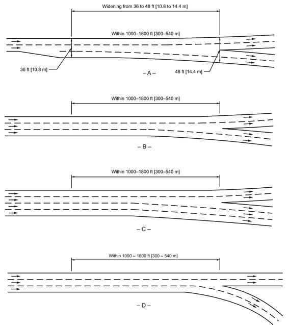
Major forks are where a freeway separates into two distinct freeways. The design of major forks is subject to the same principles of lane balance as any other diverging area. The total number of lanes in the two roadways beyond the divergence should exceed the number of lanes approaching the diverging area by at least one. Figure 7-17 illustrates four schematics for a major fork. It is important that one interior lane has an option to go in either direction. This interior lane should be widened over a distance of about 1,000-to-1,800 ft.
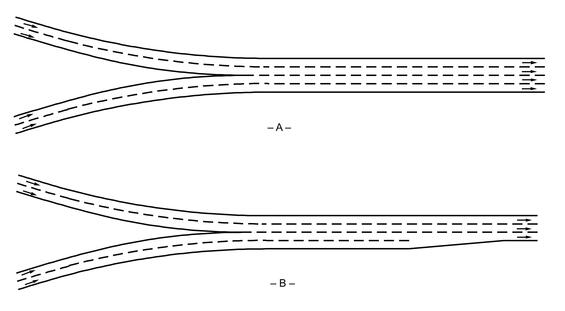
Branch connections are where two freeways converge into one freeway. Figure 7‑20 illustrates two schematics for a branch connection. When a lane is dropped, as in "B," this should be designed as a freeway lane drop (see Figure 7‑13) from the outside, not through merging interior lanes.
Merging interior lanes, or an “inside merge,” should be avoided because traffic traveling on either side of the merging lanes could prevent the merging vehicles from escaping to the adjacent lanes if they abandon the merging movement.
Figure 7-20: Major Forks
Source: A Policy on Geometric Design of Highways and Streets, AASHTO, 2018. Chapter 10 Grade Separations and Interchanges, Figure 10-78
Figure 7-21: Branch Connections
Source: Adapted from A Policy on Geometric Design of Highways and Streets, AASHTO, 2018. Chapter 10 Grade Separations and Interchanges, Figure 10-79
7.7 Ramp Design
The term ramp includes all types, arrangements, and sizes of turning roadways that connect two or more legs at an interchange. Ramp design should be compatible with safe operations on both the main highway and minor roadway and should accommodate the full transition in driving behavior. Location of ramps and intersections must consider adjacent intersections, existing, and future development.
Geometric Design
Geometric design considerations for ramps include all the elements for mainline segments. Specific elements to be considered are described below.
Design Speed
Ideally, the ramp design speeds should approximate the low-volume operating speed on the intersecting highways. Where this is not practical, the values in Table 7‑9 should be used as the minimum design speed. These design speeds apply to the ramp proper and not to the freeway/ramp junction.
If the two intersecting mainlines have different design speeds, the higher of the two should control the selection of the design speed for the ramp as a whole. However, the design speed should vary along the ramp, with the portion of the ramp nearest the lower-speed highway being designed for the lower speed.
In general, the higher range of design speeds should apply to diagonal ramps for right turns, such as at diamond and cloverleaf interchanges. The low end of the range should apply to loop ramps. Loop ramps with design speeds above 30 miles/hour require extremely large areas and greatly increase the travel distance for vehicles.
If a ramp will be terminating at an at-grade intersection with stop or signal control, the design speeds in Table 7‑10 will not apply to the ramp portion near the intersection.
For the corresponding minimum radius of the sharpest, or controlling, ramp curve, see Table 4-2.
Table 7-10: Guide Values For Ramp Design Speed (mph) by Highway Design Speed (HDS) and Speed Range
| Ramp Design Speed (mph) Range | HDS 30 | HDS 35 | HDS 40 | HDS 45 | HDS 50 | HDS 55 | HDS 60 | HDS 65 | HDS 70 | HDS 75 |
|---|---|---|---|---|---|---|---|---|---|---|
| Upper range (85%) | 25 | 30 | 35 | 40 | 45 | 50 | 50 | 55 | 60 | 65 |
| Middle range (70%) | 20 | 25 | 30 | 30 | 35 | 40 | 45 | 45 | 50 | 55 |
| Lower range (50%) | 15 | 20 | 20 | 25 | 25 | 30 | 30 | 30 | 35 | 40 |
Note: See Table 4-4 for the corresponding minimum radius (ft)
Source: Adapted from A Policy on Geometric Design of Highways and Streets, AASHTO, 2018. Chapter 10 Grade Separations and Interchanges Table 10-1
Cross Section
Figure 7‑22 and Figure 7‑23 illustrate typical ramp sections as summarized below:
- Ramp Width: The typical width is 22 ft for one-lane ramps and 30 ft for two-lane ramps.
- Cross Slope: Tangent sections of ramps should be uniformly sloped at 2.0 percent from the median edge to the opposite edge. MassDOT of has established the maximum superelevation rate at 6.0 percent.
- Side Slopes: Fill and cut slopes should be as flat as possible. If feasible, they should be 1:6 or flatter, thus eliminating the need for guardrail.
- Bridges and Underpasses: The full width of the ramp or loop should be carried over a bridge or beneath an underpass.
- Lateral Clearances to Obstructions (Clear Zones): Clear zone widths vary from 6-10 ft at 40 mph to 40-50 ft at 70 mph. The slope of the recovery area and traffic volume also plays a role in the selection of the width of the clear zone. (See the AASHTO Roadside Design Guide as a guide for determining clear zone widths for highway ramps.) Ramps should have a lateral clearance on the right outside of the edge of traveled way of at least 6 ft and preferably 8-to-10 feet, and a lateral clearance on the left of at least 4 ft beyond the edge of the traveled way.
- Exit Ramp Entrance Width: Where the through lane and exit ramp diverge, the typical width will be 25 ft. This width will be maintained until the gore nose is reached and transitioned to the standard 22 ft width at approximately a 12:1 rate.
- Entrance Ramp Terminal Width: The standard 22-ft width will be transitioned to 14-ft width at the convergence with the through lane as shown in Figure 7‑31, Figure 7‑32, and Figure 7‑33 at the end of this chapter.
Figure 7-22: Typical Sections for Ramps in Fill Areas
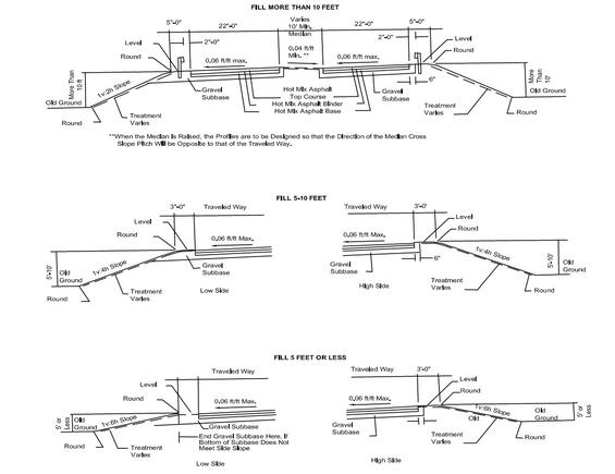
Source: MassDOT
Notes:
- The ramp pavement structure will be similar to the mainline unless otherwise noted.
- See Construction Standards Details for rounding details.
- Use hot mix asphalt berm if otherwise required for drainage.
Figure 7-23: Ramp Section in Cut Areas
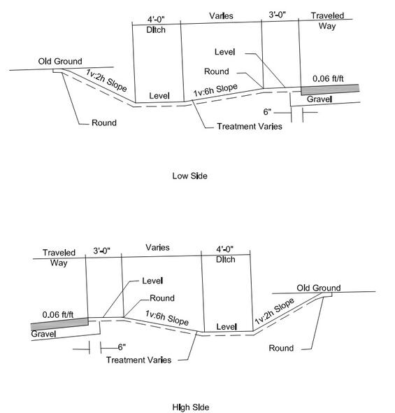
Source: MassDOT
Notes:
- The ramp pavement structure will be similar to the mainline unless otherwise noted.
- See Construction Standards Details for rounding details.
- Use hot mix asphalt berm if otherwise required for drainage.
- See Construction Standards for typical rock cut section.
- Bottom of ditch to be below bottom of subbase or provide subdrain.
Horizontal Alignment
The horizontal alignment of a ramp will largely be determined by the type of ramp and the ramp design speed, as shown in Table 7‑11 and summarized below.
- Design Speed: Ramps should be designed for minimum speeds indicated in Table 7‑10 unless restricted by site conditions.
- Outer Connection: The outer connection at cloverleaf interchanges should be as directional as possible. However, if site conditions are restrictive, it may be allowed to follow a reverse path alignment around the inner loop.
- Loops: Loop ramps should be on a continuously curved alignment in a compound curve arrangement and should follow AASHTO guidelines for length. Upper-range values of design speed generally are not attainable on loop ramps. Ramp design speeds above 30 mph for loops involve large land areas that are rarely available in urban areas. The long loop ramps needed for higher design speeds are costly and require left-turning drivers to travel a considerable extra distance. Minimum values usually control, but for highway design speeds above 50 mph, the loop design speed and the radius may be increased.
- Superelevation: MassDOT has established the maximum superelevation rate at 6.0 percent. It is preferred that the open highway conditions discussed in Chapter 4 should apply for transitioning to and from the needed superelevation. However, because of the restrictive nature of some ramps, this may not be possible. In addition, if the ramp will be terminated at an at-grade intersection with stop or signal control, it is not appropriate to superelevate curves fully near the terminus. The axis of rotation will be the profile edge.
- Sight Distance: Sight distance along a ramp should be at least as great as the design stopping sight distance. There should be a clear view of the entire exit terminal, including the exit nose and a section of the roadway beyond the gore. An object height of 0.0 ft should be used to calculate the stopping sight distance at exit areas.
- Two-Lane Ramps: See Figure 7‑24 for typical two-lane exit treatments. With development and additional traffic on freeways, the need for two-lane loop ramps has increased. The two-lane loop configuration should not be immediately preceded or followed by a loop ramp. The radius of the inner edge of the traveled way of the loop ramp normally should not be less than 180-to-200 ft. For additional design details, see the ITE Freeway and Interchange Geometric Design Handbook.
Table 7‑11: Minimum Radii for Interchange Ramp Curves
| Curve Radius Design Controls | 10 mph | 15 mph | 20 mph | 25 mph | 30 mph | 35 mph | 40 mph | 5 mph |
|---|---|---|---|---|---|---|---|---|
| Side Friction Factor, f | 0.38 | 0.32 | 0.27 | 0.23 | 0.20 | 0.18 | 0.16 | 0.15 |
| Assumed Maximum Superelevation, e/100 | 0.00 | 0.00 | 0.02 | 0.04 | 0.06 | 0.06 | 0.06 | 0.06 |
| Total e/100 + f | 0.38 | 0.32 | 0.29 | 0.27 | 0.26 | 0.26 | 0.25 | 0.25 |
| Calculated Minimum Radius R, (ft) | 18 | 47 | 92 | 154 | 231 | 340 | 485 | 643 |
| Suggested Design Minimum Radius (ft) | 25 | 50 | 95 | 155 | 235 | 340 | 485 | 645 |
Note: For design speeds greater than 45 mph, use values for open highway conditions.
Source: MassDOT
Figure 7‑24: Two-Lane Exit Terminals
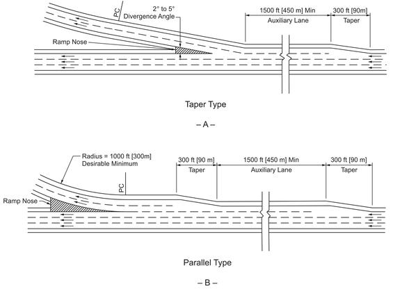
Source: A Policy on Geometric Design of Highways and Streets, AASHTO, 2018. Chapter 10 Grade Separations and Interchanges, Figure 10-77.
Vertical Alignment
Maximum grades for a ramp’s vertical alignment cannot be as definitively expressed as for the highway mainline. The minimum grade is 0.50 percent. General values of limiting gradient for upgrades are shown in Table 7‑12, but for any one ramp the selected gradient depends on multiple factors, including:
- The flatter the gradient on the ramp, the longer it will be.
- The steepest gradients should be designed for the center part of the ramp. Landing areas or storage platforms at at-grade intersections with ramps should be as flat as possible.
- Downgrades on ramps should follow the same guidelines as upgrades. They may, however, safely exceed these values by 2 percent, with 8 percent considered the desired maximum grade.
- Ramp gradients and lengths can be significantly impacted by the angle of intersection between the two highways and the direction and amount of gradient on the two mainlines.
- K values and desirable stopping sight distance should meet the minimum design values for vertical curves.
Table 7‑12: Ramp Gradient Guidelines
| Ramp Design Speed (mph) | Maximum Grade for Upgrades and Downgrades (%) |
|---|---|
| 20-25 | 6-8 |
| 25-30 | 5-7 |
| 30-45 | 4-6 |
| 45 to 50 | 3-5 |
Note: Where appropriate for topographic conditions, upgrades steeper than the desirable may be used. One-way downgrades on ramps should be held to the same general maximums, but in special cases they may be 2 percent greater.
Source: Adapted from A Policy on Geometric Design of Highways and Streets, AASHTO, 2018. Chapter 10 Grade Separations and Interchanges, Table 10-2
Capacity
The two-lane ramp capacity in Table 7‑13 is based on limited data and thus may require local calibration. However, the capacity of the actual merge or diverge junction typically controls the mainline segment capacity, not the capacity of the ramp roadway itself.
Table 7‑13: Approximate Service Volumes for Single-lane Ramps
| Ramp Free Flow Speed, SFR (mph) | Single-Lane Ramps (pc/h) | Two-Lane Ramps (pc/h) |
|---|---|---|
| >50 | 2,200 | 4,400 |
| >40-50 | 2,100 | 4,200 |
| >30-40 | 2,000 | 4,000 |
| >20-30 | 1,900 | 3,800 |
| <20 | 1,800 | 3,600 |
Source: Highway Capacity Manual, TRB, 2022. Exhibit 14-12
The Highway Capacity Manual further discusses the capacity of ramps.
7.8 Ramp/Minor Road Intersections
At service interchanges, the ramp or loop normally intersects the minor road at-grade at approximately a 90-degree angle. This intersection should be treated as described in Chapter 6. This will involve a considering the necessary traffic control devices, capacity, and physical geometric design elements (such as sight distance, angle of intersection, grade, channelization, and turning lanes). However, the following points warrant special attention when designing the ramp/minor road intersection:
- Capacity: In urban areas where traffic volumes may be high, inadequate capacity of the ramp/minor road intersection can adversely affect the operation of the ramp/freeway junction. In a worst-case situation, the safety and operation of the mainline itself may be impaired by a backup onto the freeway. Therefore, special attention should be given to providing sufficient capacity and storage for an at-grade intersection with the minor road. This could lead to the addition of lanes at the intersection or on the ramp proper, or it could involve traffic signalization where the ramp traffic will be given priority. The analysis must also consider the operational impacts of the traffic characteristics on the intersecting road and signal timing for pedestrians. The procedures described in Chapter 6 should be used to calculate capacity and level of service for the ramp/minor road intersection.
- Wrong-Way Movements: Most wrong-way movements originate at the ramp/minor road intersection. This intersection must be properly signed and designed to minimize the potential for a wrong-way movement.
- Access Restrictions: Access to abutting properties or to other local road systems will interfere with the operation and safety of the interchange. To provide efficient operations along the crossroad at an interchange, adequate lengths of access control should be part of the overall design. Doing so minimizes spillback on the ramp and crossroad approaches to the ramp terminal, provides adequate distances for crossroad weaving, provides space for merging maneuvers, and provides space for storing turning vehicles at access connections on the crossroad. Figure 7‑25 (A) illustrates the elements to be considered in determining access separation and access-control distances in the vicinity of free-flowing ramp entrances and exits. Figure 7‑25 (B) illustrates factors affecting access separation and control distances along a crossroad where ramp termini are controlled by either a traffic signal or stop sign. Access must not be permitted from ramps or from the through roadways within the entire limits of the interchange. The no-access layout line should extend a minimum distance of 100 ft in urban areas and 300 ft in rural areas from all ramp terminals. Extended areas of access control may be needed to provide adequate safety and operation of the intersections.
Figure 7‑25: Factors Influencing Length of Access Control along an Interchange
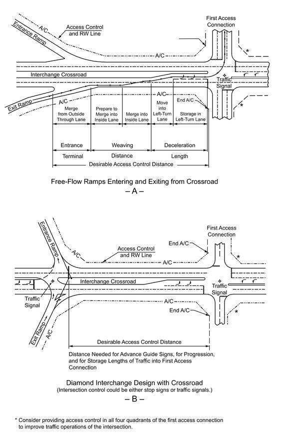
Source: A Policy on Geometric Design of Highways and Streets, AASHTO, 2018. Chapter 10 Grade Separations and Interchanges, Figure 10-2
- Sight Distance: Chapter 3 discusses the procedure for addressing sight distance at at-grade intersections. This procedure should be used for the ramp/minor road intersection. However, special attention must be given to the location of the bridge pier or abutment because these will present major sight distance obstacles. Methodologies for left-turning and right-turning vehicles presented in Chapter 3 should be used to determine if adequate sight distance is available. The combination of the bridge obstruction and the needed sight distance may result in relocating the ramp/minor road intersection to provide the needed sight distance.
- Transition: The transition between high-speed driving on the mainline and safe operating speed on the minor road should take place on the ramps. Ramp and intersection design should require the driver to adopt a safe speed before entering the minor road. Free right-turn and merge is appropriate only when an acceleration taper can be provided, otherwise a full stop is preferred, especially in areas of high pedestrian and bicycle activity. Minor road design should be consistent with adjacent sections.
- Multimodal Accommodation: The multimodal accommodation provided on the minor road should be continued through the interchange area. To improve driver response to pedestrian crosswalks and bicycle lanes, 90-degree intersections of ramps with the minor road are preferable over merge/diverge areas. With 90-degree intersections, the approaches to pedestrian and bicycle accommodation discussed in Chapter 6 are applicable.
Although full cloverleaf configurations are undesirable in areas with high pedestrian activity, crosswalks should be located so their visibility is maximized for approaching traffic and appropriate warning signs should be provided. See below for additional guidance on bike lane crossings at ramps.
Bicycle Lane Crossings at Ramps
With any ramp configuration, the designer needs to accommodate bicycle travel across the merge and diverge areas. The acute angle of a ramp approach reduces visibility. In general, 90-degree ramp intersections are preferred for bicycle accommodation and should be used in areas with expected bicycle activity when possible. Additional advance warning signage and pavement markings can be helpful.
Merging ramp areas can be challenging for people biking to traverse because the speed differential between bicyclists and motorists is high as motorists accelerate to merge into traffic. The designer should consider two approaches for accommodating bicycle travel across a ramp:
- Option 1: Provide a design that guides people biking across the ramp in a way that minimizes the crossing distance and crosses at close to a right angle, where drivers have good sightlines and their attention is not entirely focused on merging with traffic (Figure 7‑26).
- Option 2: Provide a design that allows people biking to choose their own merge, weave, or crossing maneuver (Figure 7‑27).
Considerations for choosing between these options are summarized below:
- Option 1 requires a bicyclist to yield before crossing a ramp and is best-suited to high-volume, high-speed roadways, where weaving of motor vehicle and bicycle traffic may be hazardous. This option may not be feasible where there are substantial grade changes through the interchange gore area.
- Option 2 is only suitable in low volume/low-speed environments; the cyclist and motor vehicle must weave at the merge area.
Figure 7-26: Bicycle Lane Crossing of Merging Ramp – Option 1
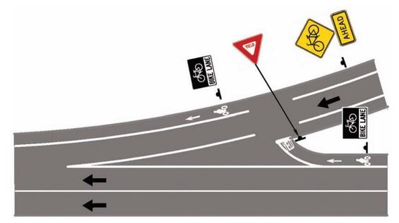
Source: Guide for the Development of Bicycle Facilities, AASHTO, 2012. Figure 4-42
Figure 7-27: Bicycle Lane Crossing of Merging Ramp – Option 2
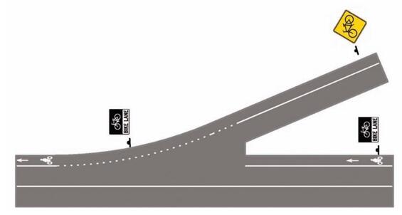
Source: Guide for the Development of Bicycle Facilities, AASHTO, 2012. Figure 4-41
Diverging ramp areas can be challenging for people biking to traverse because motorists may expect to enter the ramp without decreasing their speed, may fail to signal their maneuver, or may not yield to people biking before crossing their path of travel. The designer should consider two approaches for accommodating bicycle travel across a diverging ramp:
- Option 1: Provide a design that guides people biking across the ramp in a way that minimizes the crossing distance and crosses at close to a right angle, following the principles shown for merging ramps in Figure 7‑26.
- Option 2: Provide a right-turn lane approaching the ramp, and place the bike lane to the left of the right-turn lane. Since motorists cross the path of bicyclists to enter the right-turn lane, they are required to yield.
Figure 7-28: Freeway Exit at Interchange (Via Outer Connection of Cloverleaf-Type Ramp)
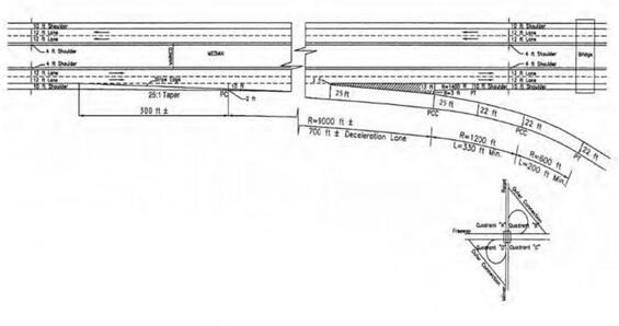
Notes:
- When the grade of the freeway is greater than 2%, increase or decrease the deceleration length according to Table 7-3.
- On the ramp beyond the gore nose, the radius of each successive compound curve should be at least 50% of the radius of the preceding flatter curve.
- The minimum length of each curve should allow sufficient deceleration distance for the design speed of the following sharper curve.
- The superelevation on the deceleration lane should be developed so that full superelevation (typically 0.06) is attained at the exit gore (PCC of R=1200 ft curve).
- 4-lane freeway is shown for illustration. This design also applies to freeways with more than 4 lanes.
- The deceleration distance shown is an example for a specific set of speeds and superelevation. Use Table 7‑1 to determine the necessary deceleration distance.
Figure 7-29: Freeway Exit at Interchange (Via Inner Loop Connection of Cloverleaf-Type Ramp)
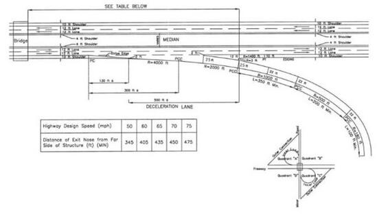
Notes:
- When the grade of the freeway is greater than 2%, increase or decrease the acceleration length according to Table 7-3.
- On the ramp beyond the gore nose, the radius of each successive compound curve should be at least 50% of the radius of the preceding flatter curve.
- The minimum length of each curve should allow sufficient deceleration distance for the design speed of the following sharper curve, if compound curvature is used.
- The superelevation on the deceleration lane should be developed so that full superelevation (typically 0.06) is attained at the exit gore (PCC of R=1000 ft curve).
- 4-lane freeway is shown for illustration. This design also applies to freeways with more than 4 lanes.
- The deceleration distance shown is an example for a specific set of speeds and superelevation. Use Table 7-1 to determine the necessary deceleration distance.
Figure 7-30: Freeway Exit at Diamond Interchange
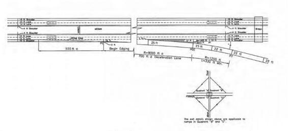
Notes:
- When the grade of the freeway is greater than 2%, increase or decrease the deceleration length according to Table 7-3.
- On the ramp beyond the gore nose, the radius of each successive compound curve should be at least 50% of the radius of the preceding flatter curve.
- The minimum length of each curve should allow sufficient deceleration distance for the design speed of the following sharper curve, if compound curvature is used.
- The superelevation on the deceleration lane should be developed so that full superelevation (typically 0.06) is attained at the exit gore (PCC of R=1200 ft curve).
- 4-lane freeway is shown for illustration. This design also applies to freeways with more than 4 lanes.
- The deceleration distance shown is an example for a specific set of speeds and superelevation. Use Table 7-1 to determine the necessary deceleration distance.
Figure 7-31: Freeway Entrance at Interchange (From Outer Connection of Cloverleaf Type Ramp)
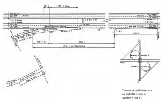
Notes:
- When the grade of the freeway is greater than 2%, increase or decrease the acceleration length according to Table 7-3.
- The method of placing the scored white cement concrete is shown on Construction Standards 105.2.0 and 105.2.1.
- The acceleration distance shown is an example for a specific set of speeds and superelevation. Use Table 7-2 to determine the necessary acceleration distance.
- A 4-lane freeway is shown for illustration. This design also applies to freeways with more than 4 lanes.
Figure 7-32 Freeway Entrance at Interchange (From Inner Connection of Cloverleaf-Type Ramp)
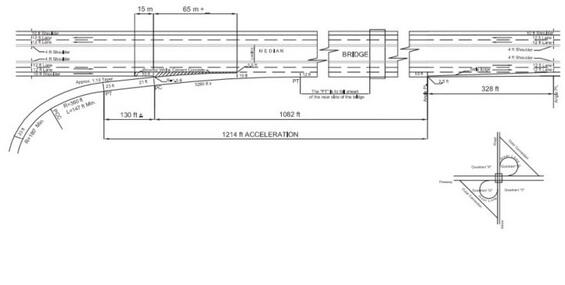
Notes:
- When the grade of the freeway is greater than 2%, increase or decrease the acceleration length according to Table 7-3.
- On the ramp beyond the gore nose, the radius of each successive compound curve should be at least 50% of the radius of the preceding flatter curve.
- The minimum length of each curve should allow sufficient deceleration distance for the design speed of the following sharper curve, if compound curvature is used.
- The superelevation on the deceleration lane should be developed so that full superelevation (typically 0.06) is attained at the exit gore (PCC of R=1200 ft curve).
- 4-lane freeway is shown for illustration. This design also applies to freeways with more than 4 lanes.
Figure 7-33: Freeway Entrance at Interchange (Diamond-Type Ramp)
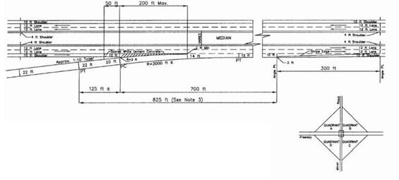
Notes:
- When the grade of the freeway is greater than 2%, increase or decrease the acceleration length according to Table 7-3.
- The method of placing the scored white cement concrete is shown on Construction Standards 105.2.0 and 105.2.1.
- This should be the minimum distance provided for acceleration regardless of the criteria from Table 7-2.
- 4-lane freeway is shown for illustration. This design also applies to freeways with more than 4 lanes.
Figure 7-34: Freeway Entrance – Exit at Interchange (Inner Loop Entrance – Inner Loop Exit of Cloverleaf-Type Ramp)
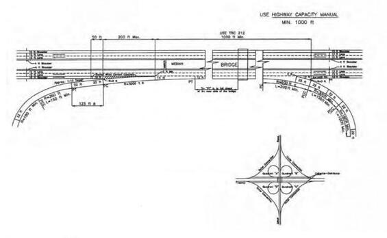
Notes:
- A Collector-Distributor road should be provided on the freeway to eliminate weaves on the mainline.
- When the grade of the freeway is greater than 2%, increase or decrease the acceleration length according to Table 7-3.
- The minimum length of each curve on the exit loop should allow sufficient deceleration distance for the design speed of the following sharper curve.
- Desirable, decision sight distance will be available to the exit gore. At a minimum, stopping sight distance will be available. See Chapter 3.
- The superelevation on the deceleration lane should be developed so that full superelevation (typically 0.06) is attained at the exit gore (PCC of R=300 ft curve).
- 4-lane freeway is shown for illustration. This design also applies to freeways with more than 4 lanes.
Figure 7-35: Partial Cloverleaf-Type Ramp/Minor Road Intersection
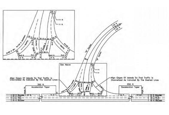
Notes:
- All islands to be edged.
- See Chapter 6 for additional details on the design of at-grade intersections.
Figure 7-36: Diamond-Type Ramp at Local Roadway
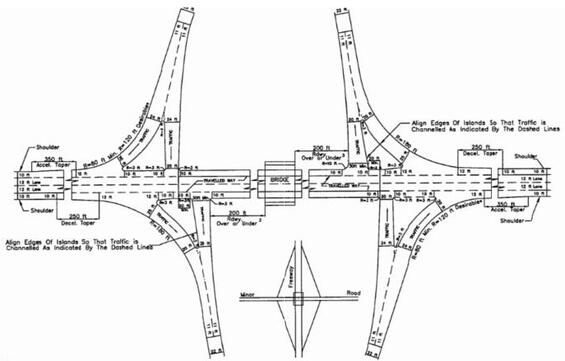
Notes:
- The directional islands and ramp medians are to be edged.
- See Chapter 6 for additional details on the design of at-grade intersections.
- 200 feet is typical. Must meet unsignalized intersection sign distance criteria.
Figure 7-37: Diamond-Type Ramp at a Local Roadway with High Levels of Bicycle and Pedestrian Activity
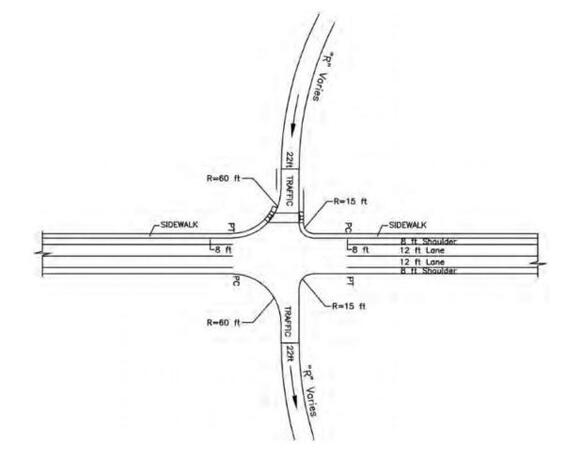
Notes:
- All islands to be edge.
- See Chapter 6 for additional details on the design of at-grade intersections.
- 8-foot usable shoulder assumed on local road.
Figure 7-38: Partial Cloverleaf-Type Ramp at a Local Roadway with High Levels of Bicycle and Pedestrian Activity
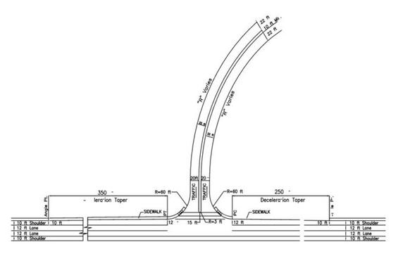
Notes:
- All islands to be edged.
- See Chapter 6 for additional details on the design of at-grade intersections.
For Further Information
- A Policy on Geometric Design of Highways and Streets, AASHTO, 2018.
- This is generally referred to as the AASHTO Green Book throughout the PDDG.
- Guide for the Development of Bicycle Facilities, AASHTO, 2012.
- Guide for the Planning, Design, and Operation of Pedestrian Facilities, AASHTO, 2014
- A Guide to Achieving Flexibility in Highway Design, AASHTO, 2004.
- Highway Capacity Manual, Transportation Research Board , 2022.
- Manual on Uniform Traffic Control Devices, Federal Highway Administration, 2009