6.1 Introduction
An intersection is an area where two or more streets join or cross at-grade. The intersection includes the areas needed for all modes of travel: pedestrian, bicycle, motor vehicle, and transit. The intersection includes not only the pavement area but also any adjacent sidewalks, off-street bicycle facilities, shared-use paths, and associated pedestrian curb ramps. Intersections are a key feature of street design in four respects:
- Focus of activity: The land near intersections often contains a concentration of travel destinations.
- Conflicting movements: Pedestrian crossings along with motor vehicle and bicycle turning and crossing movements are typically concentrated at intersections.
- Traffic control: At intersections, the movement of users is assigned by traffic control devices such as yield signs, stop signs, and traffic signals. Traffic control often results in delays to users traveling along the intersecting roadways, but helps to organize traffic and decrease the potential for conflict by accommodating traffic volumes and assigning the right-of-way.
- Capacity: In many cases, traffic control at intersections limits the roadway capacity, which is defined as the number of users that can be accommodated within a given time period.
Intersections are known points of conflict. They are a fraction of the roadway network, yet are consistently a large safety focus area for roadway owners. To improve safety at intersections for all road users, designers should use FHWA’s Safe System Approach. Embracing this approach involves incorporating roadway and intersection design features that are conducive to anticipating potential human errors, with the goal of reducing the risk of fatal or severe injuries due to collisions. To accomplish this goal at intersections, the following Safe System design strategies should be considered:
- Minimize and modify conflict points
- Reduce vehicle speeds
- Improve visibility at intersections
- Provide space and protection for pedestrians and bicyclists
Intersection Design Impacts
Intersection design affects all roadway users, as well as users of adjacent land, as described below.
Pedestrians
Key elements affecting intersection performance for pedestrians are:
- Amount of right-of-way provided for the pedestrian including both sidewalk and crosswalk width, appropriateness of slopes and cross slopes on curb ramps and walkways, and compliance with PROWAG requirements
- Audible and tactile cues for people with limited sight
- Absence of obstacles in accessible path
- Crosswalk connections
- Crossing distance and exposure to motor vehicle and bicycle traffic
- Conflicting traffic volume
- Speed and visibility of approaching traffic
- Type of traffic control
Bicyclists
Key elements affecting intersection performance for bicycles are:
- Degree to which pavement is shared or used exclusively by bicycles
- Ease of navigation for bicyclists through the intersection, including connections to facilities on segments entering and exiting the intersection
- Relationship between turning and through movements for motor vehicles and bicycles
- Traffic control for bicycles
- Differential in speed between motor vehicle and bicycle traffic
- Visibility of the bicyclist
Motor Vehicles
Key elements affecting intersection performance for motor vehicles are:
- Type of traffic control
- Vehicular capacity of the intersection, determined primarily from the number of lanes and traffic control (although there are other factors)
- Ability to make turning movements
- Visibility of approaching and crossing pedestrians and bicycles
- Speed and visibility of approaching and crossing motor vehicles
Transit
Key elements affecting intersection performance for transit are:
- Type of traffic control
- Vehicular capacity of the intersection, determined primarily from the number of lanes and traffic control (although there are other factors)
- Ability to make turning movements, if appropriate
- Location of bus stops and/or light-rail facilities
- Presence (if any) of transit-priority features, including but not limited to, signal operations and dedicated lanes
- Visibility of approaching and crossing pedestrians and bicycles
- Speed and visibility of approaching and crossing motor vehicles
Adjacent Land Uses
Owners and users of adjacent land often have a direct interest in intersection design, particularly where the intersection is surrounded by retail, commercial, historic, or institutional land uses. Primary concerns include maintenance of vehicular access to private property, turn restrictions, consumption of private property for right-of-way, and provision of safe and convenient pedestrian access.
Intersection Design Process
Once the need for intersection improvement is identified, the design of intersections follows the planning process outlined in Chapter 2. This chapter provides additional details specific to the design of intersections within the project development process. Designers should identify the intersection improvement needs and intended outcomes of the project. Design decisions can then be evaluated against those outcomes through review of related performance measures. Intersection Control Evaluations (ICE) assist in calculating and documenting the performance measures during the intersection type and traffic control design process. Performance measures should continue to be monitored during the geometric design of elements.
A key aspect of performance-based design is understanding how design elements fit together to achieve overall performance. This commonly involves balancing competing objectives, such as increasing safety performance at the expense of operational performance. In addition, design decisions regarding one element often impact other elements of the design and may have different effects on different users. By using performance measures, these design decisions can be evaluated and refined as necessary to achieve the intended outcomes.
Sections 6.2 through 6.6 define key terms and discuss intersection users, configurations, traffic control, and intersection performance. Section 6.7 describes the ranges of physical dimensions and the operational characteristics of each intersection design element.
6.2 Definitions and Key Elements
The term "intersection" encompasses not only the area of pavement jointly used by the intersecting streets but also extends to those segments of the intersecting streets affected by the design. Thus, those segments of streets adjacent to the intersection for which the cross-section or grade has been modified from its typical design are considered part of the intersection. Figure 6-1 summarizes the extent of an intersection and the relevant terminology.
- The major street is typically the intersecting street with greater traffic volume, larger cross-section, and higher functional class.
- Minor streets are one or more intersecting streets that are likely to have less traffic volume, smaller cross-section, and/or lower functional classification than the major street.
- The angle of intersection is formed by the centerlines of the intersecting streets. If the angle of intersection departs significantly (by more than approximately 20 degrees) from a right angle, the intersection is referred to as a skewed intersection.
- Intersection legs are those segments of roadway connecting to the intersection. The leg used by traffic approaching the intersection is the approach, and that used by traffic leaving is the departure.
- Thepavement edge corner is the curve or curves connecting the edges of pavement of the intersecting streets.
- Sidewalks, crosswalks, and pedestrian curb ramps are considered to be within the intersection.
Figure 6-1: Intersection Terminology

Source: MassDOT
In addition to the basic geometric design features, the following features may be added to manage service for various users.
- Auxiliary lanes are lanes added at the intersection, usually to accommodate turning motor vehicles. They may also be used to add through lanes through an intersection.
- Channelizing and divisional islands may be added to an intersection to help delineate the area in which vehicles can operate and to separate conflicting movements. Islands can also provide pedestrian refuge.
- Aturning roadway is a short segment of roadway for a right turn, delineated by channelizing islands. Turning roadways may be used where skewed intersections would otherwise create a very large pavement area, or where right-turn volumes are very high. When implemented at signalized intersections, they should also be under signal control to meet state accessibility requirements.
- Traffic control devices assign right-of-way to both motorized and non-motorized traffic. Potential traffic control devices include a range of regulatory signs, warning signs, guide and motorist information signs, pavement markings, and traffic control signals.
6.3 User Considerations
The following sections describe the characteristics of intersection users: pedestrians, bicyclists, motor vehicles, and, where applicable, public transit users. The designer should balance the needs of all modes throughout the intersection design process.
Pedestrians
All road users begin and end their trip as pedestrians. Every intersection design must consider the contextual needs of pedestrians. Pedestrians are vulnerable road users and come in all ranges of age, sex, gender, sightedness, and physical ability. Chapter 3 covers the needs of pedestrians, which include people walking or using a wheelchair, white cane, or other mobility devices. Intersection design should serve pedestrians through careful traffic control selection and treatment of conflict points with other users, especially motor vehicles. Important considerations for pedestrian movements at intersections include:
- Crossings and pedestrian curb ramp locations: Locations should correspond to the placement of sidewalks along approaching streets and likely crossing locations. Pedestrian curb ramps need to meet PROWAG requirements to ensure accessibility for people with disabilities.
- Walking speed: Refer to Chapter 3 for discussion of pedestrian walking speed.
- Traffic control, yielding, and delay: In addition to pedestrian flow capacity, pedestrians are significantly affected by the type of traffic control installed at an intersection, the specific parameters of the control, and the resulting motor vehicle operations. At stop-controlled, yield-controlled, and uncontrolled intersections, pedestrians’ ability to cross the street and the delay experienced is influenced by the yielding behavior of motor vehicles. At signalized intersections, the length and frequency of time provided for pedestrian crossings, the presence of exclusive phases versus phases shared with other modes, the clarity of information provided, conflicting turning movements, and motor vehicle yielding are key influences on pedestrians’ ability to cross the street and on delay.
Bicyclists
Bicyclists’ needs must be integrated into the design of intersections as they are vulnerable road users. Intersections are locations where bicyclists are likely traveling between facilities with varying physical separation and performing turning movements. Therefore, to improve bicyclist comfort and safety through intersection design, it is important to minimize exposure to conflict points, reduce speeds at conflict, and provide clear assignments of right-of-way to all users. When traveling with motor vehicles, bicyclists are subject to motor vehicle traffic laws. Chapter 3 covers the operating characteristics of people biking, including user types, operating width, and operating speed. Important considerations for bicycle movements at intersections include:
- Cross section: Bicyclists position themselves for their intended destination regardless of the presence of bike lanes or shoulders. If bicycle lanes are present, the design needs to ensure that bicyclists can merge to the proper location based on the bicyclist’s intended destination.
- Bicycle length: A typical upright adult bicycle is approximately 6 feet in length (the most commonly used design length). However, longer bicycle types include recumbent bicycles, tandem bicycles, bicycles with child trailers, and hand bicycles. The longest of these types is the bicycle with child or cargo trailer at approximately 10 feet (AASHTO Bike Guide 5th Edition). The designer should accommodate, to the extent possible, the adult bicycle with a child or cargo trailer in the design of queueing areas and median refuge areas.
- Design speed: Bicyclist speeds vary depending on age, ability, terrain, and facility design. On average, adult bicyclist speeds are typically between 8 and 15 mph. When approaching unsignalized intersections, bicyclists traveling along the minor street usually stop or slow and travel at speeds below this average. Adult bicyclists at a signalized intersection who have stopped for a red indication can be expected to proceed through the intersection with an acceleration rate between 2 to 5 ft/s2, with 2.5 ft/s2 as recommended default design value for flat terrain under dry conditions. Children and “interested but concerned bicyclists” tend to travel at speeds and with acceleration rates at the lower end or below these ranges. Bicyclists can be expected to decelerate on flat terrain at a rate of 5 ft/s2 under wet conditions and 10 ft/s2 under dry conditions.
- Traffic control: As with other road users, bicyclists are required to obey control devices at intersections. Therefore, traffic control devices need to account for bicycle activity. Traffic signals which operate using detection systems (such as loop detection, video camera, and microwave) should be designed and field-tested to be sensitive to bicycles. Many of the aspects of traffic control described for motor vehicles (below) also apply to bicyclists.
Additional discussion of bicyclist characteristics which impact intersection design can be found in the Intersection Design chapter of MassDOT’s Separated Bike Lane Planning & Design Guide.
Motor Vehicles
Important considerations for motor vehicle movements at intersections include:
- Vehicle characteristics: Vehicle characteristics which influence intersection design include wheelbase, turning radius, length, articulation, width, and front and rear overhangs.
- Design vehicle: The largest vehicle that is expected to frequently use a facility and make specific movements, such as through intersections or on turning roadways.
- Control vehicle: A vehicle larger than the design vehicle for which infrequent, specific movements need to be accommodated, sometimes by using multiple lanes or other means to physically fit through an intersection.
- Traffic control: Much like other users, motor vehicles are influenced by the type and timing of traffic control installed at an intersection and the number of other users. At roundabouts, stop-controlled, yield-controlled, and uncontrolled intersections, motor vehicle capacity, and delay are influenced by conflicting traffic streams. At signalized intersections, the time provided for each movement, conflicting turning movements, and the volume and mix of other users are key influences on both motor vehicle capacity and delay.
Vehicle Characteristics
Vehicle characteristics which influence intersection design include wheelbase, location of articulation, overall vehicle length, trailer length, front overhang, rear overhang, overall vehicle height, overall vehicle width including mirrors, and track width. Refer to the AASHTO Green Book and NCHRP Research Report 1061: Highway and Street Design Vehicles, An Update (2023) for definitions and further guidance.
Figure 6-2: Dimension Terminology for a Single-Trailer Combination Truck
Source: NCHRP Research Report 1061: Highway and Street Design Vehicles, An Update (2023)
Wheelbase is typically the most important vehicle characteristic governing intersection design because it dictates the wheel path on turns. Vehicles with longer secondary wheelbases (WB) have a larger turning radius which requires more pavement space and corner radius. Overhang is a critical factor in urban environments where designers need to consider objects in the right-of-way such as parked vehicles, traffic control devices, utility poles, street furniture, and signs. Figure 6-3 shows the swept path for a WB-67 interstate semi-trailer U-turn movement, where the swept path width is created by the offtracking of the rear wheels relative to the front wheels and the vehicle overhang.
Figure 6-3: Example Swept Path Plot for Interstate Semi-Trailer (WB-67)
Source: MassDOT
Semi-trailer trucks and some city buses feature an articulation in the vehicle or connection between the tractor and trailer, as seen in Figure 6-2. The kingpin to rear axle group (KPRA) dimension is the distance between the kingpin-fifth wheel connection of a tractor trailer and the center of the rear group of axles on a semi-trailer. By law, Massachusetts allows a maximum semi-trailer length of 53 feet but does not regulate KPRA. Therefore, a WB-67 configuration is allowed without a permit. However, all states bordering Massachusetts limit KPRA to 41 feet, which reflects a WB-62 wheelbase. See NCHRP Research Report 1061, Table 25, for more detail. In practice, any interstate semi-truck movements to, from, or through Massachusetts uses a WB-62 configuration and is likely the de facto configuration for freight operators in the State. Additionally, operators may slide their rear axles further forward for additional maneuverability or load balancing, which reduces the wheelbase below that of a WB-62. A WB-62 Modified is a practical interstate tractor trailer with a 53-foot trailer and is accessible in swept path software via Florida DOT’s WB-62FL vehicle configuration.
Typically, WB-67 configurations are limited to oversized loads where the excessive length needs to be balanced with a longer wheelbase (i.e., mobile home, wind turbine blades). In these cases, oversize-overweight (OSOW) permits are required. Designers can coordinate with the MassDOT Permits Office to gather historical truck information to help select appropriate design and control vehicles.
Table 6-1 below summarizes key characteristics of potential design and control vehicles. This list is not all-encompassing, because there are vehicles and configurations which may need to be tailored for context and specific movements. Vehicle dimensions and minimum turning paths are shown in Figures 6-4 through 6-14.
Table 6-1: Vehicle Types and Key Characteristics for Intersection Design
| Vehicle Type | Symbol | Length (ft) | Centerline turning Radius (ft) | Notes |
|---|---|---|---|---|
| Passenger Vehicle | P | 16.8 | 16.9 | Passenger car has been reduced with 2023 update |
| Light-Duty Pickup Truck | PU | 20.3 | 23.1 | New vehicle included with NCHRP Research Report 1061 |
| Delivery Truck | DL-23 | 22.6 | 24 | Typical parcel delivery vehicle |
| School Bus | S-BUS-36 | 35.8 | 35 | |
| City Transit Bus | CITY-BUS | 40 | 38 | Buses equipped with 3.5’ long front-mounted bicycle rack will have a wider front overhang. |
| Single-Unit Truck | SU-30 | 30 | 38 | |
| Intermediate Semi-Trailer | WB-40 | 45.5 | 36 | WB-40 is more maneuverable than SU-40 because of articulation. |
| Single-Unit Truck (three-axle) | SU-40 | 39.5 | 48 | |
| Interstate Semi-Trailer | WB-62 | 69 | 41 | |
| Interstate Semi-Trailer | WB-62 Modified | 73.5 | 41 | WB-62 Modified has the same wheelbase as a WB-62 and the same trailer length as a WB-67 (53 ft long trailer) |
| Interstate Semi-Trailer | WB-67 | 73.5 | 41 |
Note: All vehicles in this table are from the 2018 AASHTO Green Book, except PU (NCHRP Research Report 1061) and DL-23 (NACTO Urban Street Design Guide)
Source: MassDOT
Figure 6-4: Vehicle Dimensions for Passenger Car (P)

Note: Max. steering angle is 31.6°.
Source: Adapted from A Policy on the Geometric Design of Streets and Highways, AASHTO 2018, 7th Edition, Figure 2-10
Figure 6-5: Vehicle Dimensions for Light-Duty Pick-Up Truck (PU)

Note: Max. steering angle is 34.1°.
Source: Adapted from NCHRP Research Report 1061: Highway and Street Design Vehicles, An Update (2023)
Figure 6-6: Vehicle Dimensions for Delivery Truck (DL-23)

Note: Max. steering angle is 40.4°.
Source: Adapted from NACTO Urban Street Design Guide
Figure 6-7: Vehicle Dimensions for School Bus (S-BUS-36)

Note: Max. steering angle is 37.6°.
Source: Adapted from A Policy on the Geometric Design of Streets and Highways, AASHTO 2018, 7th Edition, Figure 2-16
Figure 6-8: Vehicle Dimensions for City Transit Bus (CITY-BUS)

Note: Max. steering angle is 41.4°.
Source: Adapted from A Policy on the Geometric Design of Streets and Highways, AASHTO 2018, 7th Edition, Figure 2-15
Figure 6-9: Vehicle Dimensions for Single-Unit Truck (SU-30 [SU-9])

Note: Max. steering angle is 31.8°.
Source: Adapted from A Policy on the Geometric Design of Streets and Highways, AASHTO 2018, 7th Edition, Figure 2-11
Figure 6-10: Vehicle Dimensions for Intermediate Semi-Trailer (WB-40)

Note: Max. steering angle is 20.3°.
Source: Adapted from A Policy on the Geometric Design of Streets and Highways, AASHTO 2018, 7th Edition, Figure 2-22
Figure 6-11: Vehicle Dimensions for Single-Unit Truck (3-Axle) (SB-40)

Note: Max. steering angle is 31.8°.
Source: Adapted from A Policy on the Geometric Design of Streets and Highways, AASHTO 2018, 7th Edition, Figure 2-12
Figure 6-12: Vehicle Dimensions for Interstate Semi-Trailer (WB-62 [WB-19])

Note: Max. steering angle is 28.4°.
Source: Adapted from A Policy on the Geometric Design of Streets and Highways, AASHTO 2018, 7th Edition, Figure 2-23
Figure 6-13: Vehicle Dimensions for Interstate Semi-Trailer (WB-62 Modified)

Note: Max. steering angle is 28.4°.
Source: Adapted from Florida Department of Transportation’s WB-62FL and Pennsylvania Department of Transportation’s WB-62 with 53T
Figure 6-14: Vehicle Dimensions for Interstate Semi-Trailer (WB-67 [WB-20])

Note: Max. steering angle is 28.4°. AA1 = 68.5°.
Source: Adapted from A Policy on the Geometric Design of Streets and Highways, AASHTO 2018, 7th Edition, Figure 2-24
Design Vehicle
The design vehicle is the largest type of vehicle that is expected to frequently use a road or street. An intersection will likely have a set of multiple design vehicles, one for each controlling movement. Controlling movements are described in more detail in “Selecting Design and Control Vehicles” below. Typically, design vehicles are expected to make right turning maneuvers without encroaching into opposing traffic lanes, as shown in illustration “1A” of Figure 6-15. For turns onto multilane roadways, larger design vehicles may be expected to use the full departure width (i.e., turning into an inner lane instead of the outer lane), as shown in illustration “1B” of Figure 6-15. The turns onto narrow roadways with on-street parking, larger design vehicles may be expected to use the parking lane width to complete their turn, requiring parking restrictions at intersection approaches and departures.
At intersections, the most important attributes of design vehicles are their turning radius and swept path, which influence the pavement corner radius. Wider pavement corner radii allow faster turns, impacting safety and comfort for people walking and biking. Designers are encouraged to use the smallest practical design vehicle.
Figure 6-15: Typical Design Vehicle Maneuvers
Source: MassDOT
Control Vehicle
The control vehicle is the largest vehicle for which specific, infrequent movements need to be accommodated. The control vehicle is expected to maximize the use of the intersection by encroaching into adjacent or opposing lanes, as illustrated in Figure 6-16. Encroachment may also include the use of truck aprons, cut throughs, or other intersection specific accommodations. See “Pavement Corner Radius” under Section 6.7 Geometric Design Elements for guidance on encroachment.
The control vehicle typically does not affect lane widths, pavement corner radii, and other basic geometric features of an intersection; those elements are designed to meet the needs of the design vehicle and are balanced against competing needs such as bicycle and pedestrian travel.
Figure 6-16: Example Control Vehicle Maneuver
Source: MassDOT
Selecting Design and Control Vehicles
When selecting the set of design and control vehicles, it is important to consider the context of the intersection and specific movements between facilities, as follows:
- Context
- Area type
- Roadway type
- Roadway network (ability of large vehicle to arrive at intersection and legal requirements)
- Permanent detour routes
- Transit routes
- Truck restrictions
- Truck exclusions
- Existing and planned adjacent land uses, such as commercial and industrial uses and other freight generators
- Existing traffic
- Volumes
- Vehicle classifications
- Existing vehicles characteristics
- Semi-trailer truck KPRA configuration
- School bus length
- Transit bus length
- Intersection
- Existing large vehicle movements (based on counts and/or observations)
- Future large vehicle movements (based on planned freight generators)
- Controlling movements (typically right turn)
- Presence of a high-volume driveway that functions as an intersection leg
For each intersection leg, the controlling movement is the most constrained movement by context or vehicle movement. For reconfigurations within the existing cross section, the controlling movement may be defined by objects in the right-of-way, structures, critical utilities, or other constraints. For new or widened roadway projects, the controlling movement may be defined by the largest design vehicle movement for the intersection. The controlling movement is typically a right-turn but may also be a left-turn or U-turn. Each intersection leg will typically have one controlling movement.
The designer should identify a design vehicle for each controlling movement. As such, the intersection is expected to have a set of design vehicles.
- For intersections with transit service, the designer should consider the combined service frequency of all transit routes making turns.
- For intersections with ramp terminals, the designer should consider the adjacent roadway network, area type, and freight destinations accessed by the interchange. While interstate semi-trailers are common on limited access facilities, it may not be appropriate to select a semi-trailer as a design vehicle for interchange ramp termini if the local context has a dense network of residential streets, if no freight destination is present or planned near the interchange, or if the intersecting roadway has truck restrictions. In these instances, a semi-trailer may be appropriate as a control vehicle.
The designer should identify a control vehicle for each controlling movement. For example:
- Emergency vehicles are the most common control vehicles for all intersections. The emergency vehicle (e.g., fire engine, ladder, etc.) turning characteristics should match the fleet of the local jurisdiction, consider the fire station that would likely serve the area, and be based on input from the fire department.
- Interstate semi-trailer trucks are common control vehicles at freeways interchange ramp terminals or along bypass routes for hazardous material transport.
- OSOW vehicles may be the control vehicle along trucking routes that bypass height- or weight-restricted bridges.
Table 6-2 includes example design and control vehicles for movements between the following three typical roadway cross sections:
- Narrow two-lane, which represents a local street with widths typically between 20 to 26 feet
- Wide two-lane, which represents a collector roadway or commercial street with widths typically between 32 to 50 feet
- Multilane, which represents a four-lane divided or five-lane arterial roadway with widths typically between 55 to 60 feet
The intersection approach combinations in Table 6-2 reflect a controlling movement to a similar cross section or from a larger to a smaller cross section. The example intersection configurations assume perpendicular roadways. This list is not all-inclusive, and the designer should determine appropriate design vehicles for specific intersection configurations. The narrow two-lane cross section is also representative of movements between single lane roadways.
Table 6-2: Example Design and Control Vehicles
| Intersection Approach Combinations | Example Design Vehicles | Example Control Vehicles | Common Curb Radii |
|---|---|---|---|
| Multilane to multilane |
|
| 25–30 feet |
| Multilane to wide two-lane |
|
| 25–30 feet |
| Multilane to narrow two-lane |
|
| 20–25 feet |
| Wide two-lane to wide two-lane |
|
| 20–25 feet |
| Wide two-lane to narrow two-lane |
|
| 15–20 feet |
| Narrow two-lane to narrow two-lane |
|
| 10–15 feet |
Note: This list of vehicles is not all-inclusive and does not represent a standard for selecting design and control vehicles. The designers should exercise engineering judgment when selecting design and control vehicles.
Source: MassDOT
Transit
The following characteristics of transit vehicles and transit operations should be considered in intersection design:
- Design vehicle(s): The transit vehicle(s) that operates within the intersection, whether in traffic or on fixed guideways that cross the roadway. The design vehicle appropriate for most types of transit service is the “City-Bus” as defined by AASHTO. This vehicle is 40 feet long, 8.5 feet wide, and has outer and inner turning wheel paths of 42.0 feet and 24.5 feet, respectively. The “mid-size” bus, typically accommodating 22 to 28 passengers, is also used in scheduled transit service. The turning path for the mid-size bus can be accommodated within the single-unit (SU) truck turning path. The transit design vehicle may also be an articulated bus, which is defined as the “A-BUS” by AASHTO. Transit vehicles using rail tracks, such as trolleys, have turning radii as specified by their manufacturer and are not accounted for in AASHTO templates. Their interactions with other traffic elements must be considered where applicable.
- Stop locations: See detail below.
- Signal priority for transit vehicles: These include transit signal priority (TSP) strategies and queue jump facilities that use special transit signals to prioritize the movement of transit vehicles through intersections.
Stop Locations
Transit stops are often located at intersections either as a near-side stop on the approach to the intersection or as a far-side stop on the departure leg of the intersection. Location near intersections is recommended to facilitate round-trip travel by people riding transit, given that each travel direction will be on opposite sides of the street and require the transit rider to cross the street. Stop locations near intersections are also advantageous where transit routes intersect, minimizing the walking distance to make a transfer.
A bus stop, whether near-side or far-side, typically requires 65 to 110 feet of curb space unencumbered by parking. On streets without parking lanes or bus bays, buses must stop in a moving traffic lane to service passengers. Passengers typically require 4 to 6 seconds per person to board a bus, and 3 to 5 seconds per person to disembark. The total amount of time a transit vehicle will block traffic movements can then be estimated using the number of boardings and alightings expected at a stop.
Designers should work with the applicable Regional Transit Authority during project development to ensure their specific operational needs are met for new or reconstructed transit stops and for specific design guidance, such as the MBTA’s Bus Stop Planning and Design Guide.
Signal Priority for Transit Vehicles
For guidance on TSP and queue jump design, designers should refer to the MBTA’s Transit Signal Priority Treatments chapter in the Bus Priority Toolkit.
6.4 Intersection Types and Configurations
Intersections can be categorized into four major types, as illustrated in Figure 6-17:
- Simple
- Flared
- Channelized
- Roundabout
Figure 6-17: Intersection Types
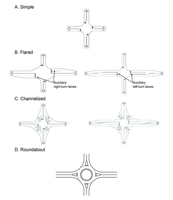
Source: Adapted from A Policy on the Geometric Design of Streets and Highways, AASHTO 2018, 7th Edition, Figure 9-7, Figure 9-8; Adapted from A Policy on the Geometric Design of Streets and Highways, AASHTO 2004
Simple Intersections
Simple intersections maintain the street’s typical cross section and number of lanes throughout the intersection, on both the major and minor streets. Simple intersections are best suited to locations where auxiliary (turning) lanes are not needed to achieve the desired level of service or are infeasible due to nearby constraints. Generally, simple intersections provide the minimum crossing distances for pedestrians and are common in low-volume locations.
Flared Intersections
Flared intersections expand the cross section of one or more intersecting streets. The flaring is often done to accommodate a left-turn lane, so that motor vehicles are removed from the through traffic stream to increase capacity at high-volume locations and safety on higher speed streets. Right-turn lanes, less frequently used than left-turn lanes, are usually a response to large volumes of right turns.
Intersections may be flared to accommodate an additional through lane as well. Auxiliary through lanes originate in advance of the intersection and terminate beyond the intersection, with users merging back into the adjacent lane. This approach may be effective in increasing capacity at isolated rural or suburban settings in which lengthy widening beyond the intersection is not needed to achieve the desired level of service, not feasible due to nearby constraints, or not desirable within the context of the project.
Intersection approaches can be flared slightly, not enough for additional approach lanes but through a combination of offset and curb radius to reduce the encroachment of a turning design vehicle into adjacent lanes. The combination of offset and larger turn radius may also allow a passenger vehicle to turn at a higher rate of speed, which negatively impacts the safety and comfort of pedestrians and bicyclists. Flares also increase the pedestrian crossing distance, increasing exposure in the roadway and increasing the pedestrian clearance time requirements.
Channelized Intersections
Channelized intersections use pavement markings or raised islands to designate the intended vehicle paths. The most frequent use is for right turns, particularly when accompanied by an auxiliary right-turn lane. At skewed intersections, channelization islands are often used to facilitate right turns for design vehicles, even in the absence of auxiliary right-turn lanes. Right-turn channelizing islands can provide refuge for pedestrians but may result in higher turning speeds for motor vehicles. Additionally, uncontrolled right turns or yield-controlled right turns at higher speeds may result in drivers yielding less to pedestrians.
Divisional islands can help direct drivers to and through the intersection. Median islands that are of sufficient width may also be used for pedestrian and bicyclist refuge, allowing a pedestrian or bicyclist to cross one half of the roadway at a time. If this type of two-stage crossing is intended, these islands should be wide enough to allow for comfortable storage of the anticipated volume of all intended user types and of sufficient width to meet PROWAG requirements for the placement of detectable warning surfaces.
Channelization islands are also used in support of left-turn lanes, forming the ends of the taper approaching the turn bay, and often the narrow divisional island extending to the intersection. At “T”-type intersections, a channelization island can guide oncoming traffic to the right of the left-turn lane.
Channelization, particularly at smaller intersections, can benefit pedestrians by allowing them to cross in multiple stages, having to monitor only one direction of traffic with each crossing. The design of the channelization, whether right-turn or divisional islands, should consider the needs of pedestrians. Pedestrians who use wheelchairs need cut-throughs or ramps and the associated landing areas. Designers must also consider how people with vision impairments would navigate the channelized intersections.
Roundabouts
The roundabout is a channelized intersection with one-way traffic flow circulating counterclockwise around a central island. Entering traffic must yield to circulating traffic. Although usually circular in shape, the central island of a roundabout can be oval or irregularly shaped.
Roundabouts may be a preferred design alternative to both stop-controlled and signal-controlled intersections, as they have fewer conflict points than traditional intersections and are designed to promote slow motor vehicle speeds, which benefits all users. While crossing a roundabout, pedestrians need to cross only one direction of traffic at a time for each approach. Although the number of vehicle-pedestrian conflict points is generally unaffected, vehicles come from a more defined path, providing pedestrians with fewer locations to check for oncoming vehicles. At intersections of two-lane streets, roundabouts can usually function with a single circulating lane, making it possible to fit them into most settings.
MassDOT has adopted Guidelines for the Planning and Design of Roundabouts. This provides guidance on design principles and features of roundabouts in consideration of all user types.
Typical Intersection Configurations
Examples of intersection configurations frequently encountered by the designer are shown in Figure 6-18. Offset intersections are those with adjacent T intersections that function similar to a four-leg intersection. Most intersections have three or four legs, but intersections with five or more legs are not unusual.
Ideally, streets in three-leg and four-leg intersections cross at right angles or nearly so. However, skewed approaches are a regular feature of intersection design. When skew angles are substantially different from 90 degrees, the designer should evaluate intersection modifications to reduce the skew.
Figure 6-18: Intersecting Street Configuration and Nomenclature

Source: Adapted from A Policy on the Geometric Design of Streets and Highways, AASHTO 2004
Indirect Intersection Configurations
Indirect intersection configurations are those where one or more movements are executed at a location away from the primary intersection. Often, the indirect movement is a left turn. The vehicle can be redirected through a right-turn and a U-turn, such as at a restricted crossing U-turn or median U-turn. It can also be redirected to complete the left turn at a point on the minor road away from the primary intersection through the use of a jughandle or a quadrant roadway.
Alternative intersections are a group of intersection configurations that includes indirect intersection configurations. FHWA and NCHRP have multiple guides providing design guidance for these intersections including:
- Alternative Intersections/Interchanges Informational Report
- Restricted Crossing U-Turn Intersection Informational Guide
- Median U-Turn Intersection Informational Guide
- Diverging Diamond Interchange Informational Guide
- Displaced Left-Turn Intersection Informational Guide
- Quadrant Roadway Intersection Informational Guide
6.5 Intersection Control
Traffic control devices, such as traffic signals, STOP signs, or YIELD signs, along with supporting pavement markings, typically control the entry of vehicles into the intersection. Traffic control devices may also be required at intersections of important private driveways with public streets. Examples of important driveways include, alleys serving multiple homes, commercial alleys accessing parking, and commercial driveways.
Generally, in selecting the preferred type of traffic control, the primary measures of consideration include safety concerns and the volume of motor vehicles, bicycles, and pedestrians. For intersections with lower volumes, STOP control on the cross (minor) street is the most frequently used form of vehicular traffic control.
MassDOT has adopted an Intersection Control Evaluation (ICE) Procedure for evaluating locations to determine the most effective form of intersection control at any new or reconstructed intersections. The ICE Procedure considers roadway context and users and provides recommendations for intersection control strategies based on safety, mobility, and operations.
6.6 Intersection Performance Measures
Intersection performance can be measured in many ways. The most common intersection performance measures can be grouped into two main categories: safety performance and operational performance.
Safety Performance
As discussed in Chapter 1, the Safe System Approach is a guiding principle in project development and design in the Commonwealth. Chapter 3, Section 3.3 describes how the Safe System Approach supports MassDOT’s commitment to zero roadway deaths and serious injuries. The design of intersections directly influences the safety of roads.
The Highway Safety Manual (HSM) provides quantitative methodologies to estimate safety performance measures. Through this methodology, safety benefits can be quantified based on estimated future crashes, expected change in safety performance, and crash costs. The MassDOT Safety Alternatives Analysis Guide describes the quantitative safety performance methodology.
Future crashes can be calculated using either expected, predicted, or observed crash frequency:
- Observed crashes are the actual crashes reported to have occurred at the study site.
- Predicted crashes refer to the predicted crash frequency at a study site obtained from a safety performance function.
- Expected crashes refer to the expected crash frequency given existing conditions at a study site and the historical safety performance at many similar sites.
- This is a weighted average of observed and predicted crash frequency and is calculated using the Empirical Bayes method.
The expected change in safety performance is determined by applying Crash Modification Factors (CMFs) to the future predicted or expected crashes. Crash frequencies can comprise one or more user types, crash types, crash severities, or a combination of these. Safety savings can be inferred by assigning average comprehensive crash costs to the estimated crash reduction
When the HSM methodologies cannot be applied, other options may be available including using the Safe System for Intersections (SSI). Depending on the intersection, a quantitative safety performance may not be possible. Regardless of the methodology used, the Safe System Approach’s principles and elements should be considered throughout design.
Operational Performance
The Highway Capacity Manual (HCM) defines and provides qualitative and quantitative procedures for estimating operational performance measures for a variety of intersection forms.
Operational performance involves assessing how projected demand for each mode to use an intersection compares to the ability for the intersection to serve each movement. If the projected demand for a given movement exceeds the ability for the intersection to serve that movement (its capacity), then the observed volume that passes through the intersection (served volume) will be less than the demand. In such cases, the excess demand may queue up at the intersection, divert to other routes, or change behavior in other ways (e.g., travel at other times, travel by other modes).
Operational performance measures can be grouped into measures of quality of service and measures of capacity. The following sections discuss each of these, along with a simplified method for assessing capacity at a signalized intersection.
Quality of Service and Level of Service
The HCM defines “quality of service” as “a description of how well a transportation facility or service operates from a traveler’s perspective.” The HCM lists a variety of factors that influence traveler-perceived quality of service, including travel time, speed, and delay, number of stops incurred, travel time reliability, comfort, safety (actual or perceived), and others (HCM 7th Edition).
For each facility type, the HCM selects one or more performance measures—defined as “service measures”—to represent the “level of service” (LOS) for each type of intersection user and each facility type. LOS is a stratification of quality of service into a set of letter grades from A to F, with each letter grade corresponding to a range of values for the selected performance measure.
For motorized vehicles at individual intersections, LOS is assigned based on the amount of control delay encountered by the user at the intersection. Control delay, a result of traffic control devices needed to separate the potentially conflicting flows at the intersection, reflects the difference between travel time through the intersection at free flow versus travel time under the encountered conditions of traffic control. For drivers, control delay includes time needed to decelerate for the traffic control device (or to join a queue), time advancing through a queue and waiting at the traffic control device, and time accelerating back to free-flow speed. For pedestrians and bicyclists, deceleration and acceleration times are insignificant, and control delay is largely the time spent waiting at signals, STOP, or YIELD signs. Because control delay increases exponentially as volume approaches capacity, LOS degrades correspondingly.
For assessing urban streets as a series of intersections or for assessing interchanges and alternative intersection forms, average travel speed, travel time, or extra distance, travel time are often considered in addition to control delay. These account for geometric conditions, including distance between intersections, geometric delay for through movements at roundabouts, and other factors. The HCM provides further discussion of these performance measures.
For pedestrians and bicyclists, the performance measures used to determine LOS depend on the control type present at the intersection.
- At signalized intersections, pedestrian LOS is a function of conflicting motorized vehicle volumes and speeds, crosswalk length, average pedestrian delay, and the presence of right-turn channelizing islands. Pedestrian LOS improves with lower motorized vehicle volumes and speeds, shorter crosswalk lengths, lower delay, and the presence of right-turn channelizing islands.
- At signalized intersections, bicycle LOS is a function of perceived separation from motor vehicle traffic, motorized vehicle volumes, cross-street width, and presence and use of on-street parking. Bicycle LOS improves with greater perceived separation from motorized vehicle traffic, lower motorized vehicle volumes, shorter cross-street widths, and reduced on-street parking conflicts.
- At two-way stop-controlled intersections, only pedestrian LOS is defined. It is a function of delay and specific crossing treatments such as crosswalk markings and median refuges.
Capacity
The HCM defines capacity as “the maximum sustainable hourly flow rate at which persons or vehicles reasonably can be expected to traverse a point or a uniform section of a lane or roadway during a given time period under prevailing roadway, environmental, traffic, and control conditions.” (HCM 7th Edition). If needed, the HCM provides additional detail on the capacities of individual modes, such as pedestrian and bicycle flow capacities. “Capacity” (loosely, the maximum possible flow) differs importantly from “service volumes” (flows associated with the quality of flow, typically associated with a specific LOS).
The factors that influence capacity vary based on the type of traffic control. At unsignalized intersections, motorized vehicle capacity is governed by the ability of motor vehicles (on the minor street or of major street left turns) under stop-control or yield-control to enter or cross the stream of moving motor vehicles on the major street. The HCM provides procedures for estimating the capacity of each minor movement as a function of turning movement volumes, gap acceptance characteristics, impedance by higher ranking movements, and other factors. Further increases in intersection capacity at stop-controlled or yield-controlled intersections can be gained by replacing stop or yield control with signal control or a roundabout. At signalized intersections, motor vehicle capacity is governed by the number of lanes approaching the intersection, the number of receiving lanes, signal phasing, and the amount of green signal time given to the approach. The total green time available decreases as the number of critical signal phases increases.
Operational Assessment Techniques
The HCM provides a series of planning and operational assessment methodologies that can assess a wide variety of commonly encountered situations. However, sometimes the conditions being analyzed extend beyond the capabilities of the HCM methods, and other software tools may be better suited for such analyses. The HCM provides a detailed list of capabilities and limitations of each methodological chapter. Examples of cases where limitations of the HCM methodologies may support the use of other software tools include the following:
- Analysis of lane configurations that are not covered by HCM procedures, such as three-lane entries at roundabouts
- Analysis of diversion to other routes due to conditions being severely over capacity
- Analysis of advanced operational or detection systems used at signalized intersections, such as preemption or transit signal priority
- Analysis of closely spaced intersections where queues from one intersection extend into or beyond another intersection of interest
Further guidance on selecting and using a variety of analysis tools, including selecting appropriate traffic analysis tools and guidelines for applying microsimulation, can be found in FHWA’s Traffic Analysis Toolbox.
The HCM provides a series of methods for estimating the capacity of intersections with various forms and control types. For signalized intersections, the HCM provides a detailed operational analysis method that calculates performance measures based on a wide variety of inputs. However, in many cases a simplified method from the HCM—the HCM Planning-Level Assessment—can be used to answer a variety of common questions, including the following (adapted from HCM 7th Edition, Chapter 31, Section 5):
- Is an intersection’s lane geometry sufficient to accommodate a given set of turn-movement demand volumes?
- How would aggregate changes in geometry (e.g., adding a lane) affect operational performance?
- How do signal phasing and timing affect operational performance?
- How does a signalized intersection compare to other intersection controls and forms?
The HCM Planning-Level Assessment forms a simplified core to the overall HCM procedure and is also the basis for the simplified methods used in FHWA’s CAP-X assessment tool to support Intersection Control Evaluation. Refer to MassDOT Intersection Control Evaluation for additional information.
The HCM method has its origins in the TRB Circular 212 method (1980) and has been adapted for compatibility with the current HCM operational method. The HCM method has two parts: (1) assessing capacity, and (2) determining delay and level of service. The first part, consisting of five steps, is used to assess intersection sufficiency (i.e., how close to capacity is it expected to operate?) and is often sufficient to answer the questions identified above. The five steps are as follows:
- Determine left-turn operation, such as protected-only, protected-permissive, permissive-only, or split phasing. This is either known or must be assumed based on volume levels and other factors. The HCM provides guidance for cases where left-turn phasing is unknown.
- Convert movement volumes to through passenger–car equivalents. This accounts for the effect of heavy vehicles, variations in flow during the hour, impacts of opposing through vehicles on permissive left turns, and other factors. For simple cases with protected left-turn or split phasing and low truck volumes, this step can often be skipped.
- Assign flow rates to lane groups. Lane groups may be single lanes or groups of lanes that function together as a unit, such as a double left-turn movement or a through and shared-through-right movement. In this step, volumes are divided by the number of lanes associated with each lane group.
- Determine critical lane groups. Some lane groups conflict with other lane groups and must operate sequentially, such as a northbound protected left-turn and the opposing southbound through movement. The critical lane groups consist of the sequence of lane groups that have the highest volume and thus dictate the overall operation of the intersection.
- Determine intersection sufficiency. In this final step, the critical lane group flow rates are added together and divided by the intersection’s capacity to calculate a critical intersection volume-to-capacity ratio. If local data on cycle length and base saturation flow rate are unknown, a default intersection capacity of 1,650 through passenger cars per hour per lane can be used. The result is a capacity assessment of “under” (critical intersection volume-to-capacity ratio <0.85), “near” (0.85-0.98), or “over” (>0.98).
Computing Critical Lane Volume
For a typical four-leg intersection, the critical-lane flow rate, known as critical lane volume (CLV), is the sum of main street CLV plus the cross street CLV.
- The main street CLV is the greater of either: (A) eastbound through and right per lane+ westbound left OR (B) westbound through and right per lane+ eastbound left.
- Similarly, the cross street CLV is the greater of either: (A) northbound through and right per lane+ southbound left OR (B) southbound through and right per lane+ northbound left.
The following example, illustrated in Figure 6-19 and Figure 6-20, demonstrates the key calculations in Steps 3 and 4 of the HCM method summarized above for a simple case of protected left-turn movements on all approaches. In the example, the total intersection CLV is 870. Using an assumed intersection capacity of 1650, the critical intersection volume-to capacity ratio is 870 / 1650 = 0.53. Because this is less than 0.85, HCM guidance assesses this as "under" capacity.
The example main street CLV (shown in Figure 6-19) is the larger of either sum:
- Eastbound through per lane and right turn (divided by number of lanes in lane group) + opposing left turns: (620 + 60) ÷ 2 + 50 = 390
- Westbound through per lane (divided by number of lanes in lane group) + opposing left turns: (460 + 70) ÷ 2 + 80 = 345
Main street CLV is therefore 390.
The example cross street CLV (shown in Figure 6-20) is the larger of either sum:
- Northbound through per lane and right turn + opposing left turns: (410 + 30) +40 = 480
- Southbound through per lane + opposing left turns: (280 + 10) + 20 = 310
Cross street CLV is therefore 480.
Total intersection CLV = main street CLV + cross street CLV = 390 + 480 = 870
Figure 6-19: Computing Critical Lane Volume on the Main Street

Source: Transportation Research Board, Circular Number 212, TRB 1980.
Figure 6-20: Computing Critical Lane Volume on the Cross Street

Source: Transportation Research Board, Circular Number 212, TRB 1980.
Assessing Other Intersection Types
At roundabouts, motor vehicle capacity is governed by the ability of entering traffic to enter the stream of motor vehicles in the circulating roadway. The HCM provides analysis procedures for estimating the performance of one-lane and two-lane roundabouts and guidance for other cases. For additional information on this topic, refer to the HCM and to the MassDOT Guidelines for the Planning and Design of Roundabouts.
The HCM also provides planning-level and operational-level assessment for other types of intersections and interchanges, including two-way stop-controlled intersections, all-way stop-controlled intersections, a variety of diamond and partial cloverleaf interchange forms, and a variety of alternative intersection forms where turning movements are reassigned, such as median U-turn (MUT) intersections and restricted crossing U-turn (RCUT) intersections. These procedures are discussed further in the HCM.
6.7 Geometric Design Elements
The following sections describe many of the detailed design elements associated with intersections including intersection alignment, pavement corner radii, auxiliary lanes, channelization islands, median openings, pedestrian curb ramps and crosswalks, bicycle lane treatments, and bus stops.
Intersection Alignment
Intersection alignment guidelines control the centerlines and grades of both the major and minor streets, in turn establishing the location of all other intersection elements (for example, edge of pavement, pavement elevation, and curb elevation).
Horizontal Alignment
Streets should intersect as close to a 90-degree angle as practical, but not less than 75 degrees. Measurement of the angle of intersection is shown in Figure 6-21. Skewed intersections can reduce visibility of approaching motor vehicles and bicycles, require higher degrees of traffic control, require more pavement to facilitate turning vehicles, and require greater crossing distances for pedestrians.
Curvature through an intersection affects the sight distance for approaching motorists and may require additional traffic control devices or a change in intersection form (warning signs, stop signs, signals, pavement markings, or conversion to a roundabout). On higher-speed roads, superelevation on curves may incline the cross slope of the intersection in a manner uncomfortable to motorists or in conflict with intersection vertical alignment guidelines described below.
Often, in steep terrain, a permissible grade cannot be achieved with the horizontal alignment guidelines. Typically, this design challenge is resolved by adhering to vertical alignment criteria while incorporating the necessary flexibility in the horizontal guidelines.
Figure 6-21: Horizontal Alignment Guidelines at Intersections

Source: MassDOT
Vertical Alignment
The major street and minor street profile influence the vertical alignment of an intersection.
Major Street Profile
Approach grade has varying effects on different users. In the uphill direction, gravity reduces the acceleration rate of motor vehicles and increases the effort of bicyclists starting from a stopped condition. In the downhill direction, gravity increases the stopping distance required for approaching motor vehicles and the speed of approaching bicycles.
The intersection grade is the slope of the pavement within the intersection itself. Excessive intersection grade can cause tall vehicles (trucks, buses) to tip while turning. Intersection grade can also have an impact on accessibility for pedestrians with disabilities by creating a grade on crosswalks. In conformance with PROWAG, the grade of the roadway at a pedestrian crossing (the cross slope from the pedestrian’s perspective) at uncontrolled approaches as well as those under traffic signal control shall not exceed five percent. Additionally, the cross slope or superelevation of the roadway at a pedestrian crossing (the grade from the pedestrian’s perspective) shall generally not exceed five percent, but may match the roadway superelevation.
The length of vertical curves between the non-intersection grade and the intersection approach grades is governed by the guidelines for vertical alignment discussed in Chapter 4.
Minor Street Profile
The profile of the minor street, as shown in Figure 6-22, is subject to the same vertical alignment criteria as the major street. However, several inherent features of a minor street, particularly its lower level of usage, will most likely permit a lower design speed for the minor street compared to the major street.
Where the minor street is under STOP- or YIELD-control (Figure 6-22, Part A), the crown of the major street is typically carried through the intersection. Meeting this major street cross section can result in minor street grades near the intersection that are steeper than that which would occur with the major street crown removed.
At intersections where the major street retains the crown through the intersection, the minor street crown is gradually reduced, typically starting at the beginning of the approach grade, and completed slightly outside the intersection.
At intersections with signal control, it is customary to remove the crown from both the major street and the minor street. This removal of the crown is advisable for the comfort and safety of motor vehicle drivers and bicyclists proceeding on either street at the design speed through a green signal indication. At intersections with all-way STOP control, it may be desirable to remove the crown from both intersecting streets, to emphasize that all approaches are equal in terms of their traffic control.
Eliminating the crown on the major street can, under many circumstances, reduce the amount of modification that must be done to the minor street profile. The major street cross slope can be inclined in the same direction at the minor street profile, thereby permitting approach grades on the minor street to be accommodated with minimal alteration to the original minor street profile. Where both major street and minor street crowns are eliminated, their removal is accomplished gradually, typically over the length of the approach grade. Whether crowned or not, pavement grades within the intersection should not exceed the values given in Figure 6-22.
In addition to meeting the vertical profile guidelines as stated above, intersection approaches on both major and minor streets are subject to the intersection sight triangle requirements (see Chapter 3). Under some circumstances, these sight triangle requirements may dictate approach grades or length of approach grades differing from those indicated in the vertical alignment guidelines above. In addition, pedestrian crossings must comply with PROWAG requirements, which vary depending on the type of control used at the intersection.
Figure 6-22: Pavement Cross Slope at Intersections
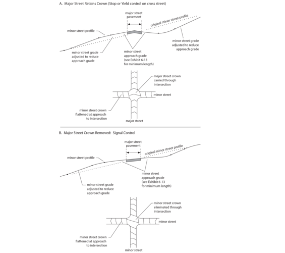
Source: Transportation Association of Canada
Pavement Corner Radius
The pavement corner radius—the curve connecting the edges of pavement of the intersecting streets—is defined by either the curb or, where there is no curb, by the edge of pavement.
The pavement corner radius is a key factor in the safety and operational performance of the intersection, through its:
- Direct effect on vehicle turning speeds, which influence yield rates, severity of potential rear-end collisions between turning and through vehicles due to a higher speed differential, and severity of potential collisions between turning vehicles and vulnerable roadway users
- Direct effect on pedestrian crossing distance/exposure
- Indirect effect on signal timing
The pavement corner radius also affects the surrounding built environment, including effective sidewalk width and right-of-way impacts.
The designer should develop the pavement corner radii to accommodate the design vehicles minimum inside radius turning path, as defined in Section 6.3: User Considerations. If an outside truck apron is necessary, the designer should develop the roadway curb radius, as illustrated Figure 6-1 above and Figure 6-24 below, to accommodate the control vehicle minimum inside radius turning path. See “Corner Truck Aprons” below for more information.
The designer should follow the workflow below to develop the pavement corner radii:
- Select design vehicles and control vehicles
- Determine appropriate encroachment scenarios
- Determine appropriate pavement corner radii using design vehicle movements
- Test critical control vehicle movements, set the curb radii, and implement additional accommodation (e.g., corner truck apron)
- Adjust curb radii and encroachment scenarios, if necessary
Encroachment
Encroachment is when a vehicle enters adjacent or opposing travel lanes. Encroachment also refers to when a vehicle departs the paved roadway to complete a turning maneuver. The designer should consider the context (e.g., volume, speed, sight distance, traffic control) to determine what degree of encroachment is appropriate for an intersection.
Figure 6-23 identifies the possible combinations of encroachment into adjacent and opposing lanes of the approaching and receiving legs. It also illustrates the likely combination of single and multilane intersection layouts where these encroachment scenarios are typically encountered. Encroachment into adjacent lanes is only applicable to multilane roadways. Encroachment into adjacent or opposing lanes on the approach leg is not preferred, because encroaching into adjacent lanes creates the risk of smaller passenger vehicles entering into the blind spot of an articulated vehicle. The designer must confirm the acceptable degree of encroachment during the project development process. To the extent possible, the designer should start with lower degrees of encroachment and, if necessary, allow for more encroachment on the receiving leg before encroaching on the approaching leg (i.e., adjust the encroachment scenario from 1B to 1C before adjusting from 1B to 2B) as appropriate. Encroachment may be paired with modifications to pavement markings (e.g., shifting stop bars further from the intersection) as appropriate. In urban and town center contexts and for maneuvers from multilane (often arterial) roadways onto single lane (often local) roadways, a higher degree of encroachment may be expected.
Figure 6-23: Intersection Maneuvers and Encroachment Scenarios
Source: MassDOT
Additional considerations for each maneuver type are summarized below:
- 1A – Stay in lane on approach and receiving legs (No encroachment)
- Expected of the design vehicle
- 1B – Stay in lane on approach and encroach into adjacent receiving lane
- Expected of articulated design vehicles onto multilane roadway sections
- 1C – Stay in lane on approach and encroach into opposing receiving lane
- Typical when the receiving roadway is a two-lane section
- Appropriate when receiving roadway is controlled
- At signals, typically accommodated by marking the receiving leg stop bar further from intersection
- May not be appropriate when sight lines are restricted
- 2A – Encroach into adjacent approach lanes and stay in lane on receiving leg
- Not preferred because of the blind spot risks discussed above
- May be necessary when turning onto single-lane, one-way roadways in urban contexts
- 2B – Encroach into adjacent approach lanes and encroach into adjacent lanes on receiving leg
- Not preferred because of the blind spot risks discussed above
- May be appropriate in urban contexts where modifications to existing curb lines and/or medians are not an option
- Typically reserved for tractor trailers
- Not appropriate on high-speed, signalized approaches
- Considered a "straddle-lane" design at multilane roundabouts
- 2C – Encroach into adjacent approach lanes and encroach into opposing lanes on receiving leg
- Not preferred because of the blind spot risks discussed above
- May be appropriate in urban contexts where modifications to existing curb lines and medians are not an option
- Not appropriate when the receiving roadway is uncontrolled.
- 3A – Encroach into opposing lanes on approach and stay in lane on receiving leg
- Not preferred because of the blind spot risks discussed above
- May be necessary when turning onto single-lane, one-way roadways in urban contexts or onto a divided receiving roadway
- 3B – Encroach into opposing lanes on approach and encroach into adjacent lanes on receiving leg
- Not preferred because of the blind spot risks discussed above
- May be appropriate in urban contexts where modifications to existing curb lines and medians are not an option
- 3C – Encroach into opposing lanes on approach and encroach into opposing lanes on receiving leg
- Only appropriate if sufficient gaps are available in the opposing traffic flow or if opposing traffic flow is stopped by a stop sign or a signal (e.g., split phasing)
The designer should use encroachment as a tool to reduce the corner curb radius. All scenarios other than 1A and 1B are maneuvers expected of control vehicles. The designer should balance and adjust encroachment alongside other tools like curb radius and curb and taper combinations. The designer should use design vehicles presented in Section 6.3 User Considerations or vehicle turning templates presented in AASHTO’s Green Book using appropriate software to confirm appropriate pavement corner designs.
For information on encroachment at driveways, see Chapter 15.
Pavement Corner Radius Configurations
At the majority of all intersections, the pavement corner design is dictated by the right-turn movement. Left turns are seldom a critical factor in corner design except at intersections of two one-way streets, in which case, their corner design is similar to that for right turns at intersections of two-way streets. The method for pavement corner design can vary as shown in Figure 6-24 and described below:
- Simple pavement radius: In most settings, a single radius is the preferred design for the pavement corner. A single radius sized for the design vehicle will control motor vehicle speeds, minimize the crosswalk distance and intersection footprint, and is simpler to design and construct.
- Compound curves or combinations of curves and tapers: Where encroachment by the design vehicle into adjacent lanes must be avoided or where the angle of turn is greater than 90 degrees, compound curves can define the pavement corner edge. Combinations of tapers with a single curve that closely fit the right rear-wheel vehicle track are generally acceptable. Combinations of curves and tapers are typically reserved for high speed, rural applications.
- Turning roadways: A separate right-turn lane, usually delineated by a channelization island may be appropriate where right-turn volumes are large, or where the design vehicle has a wide turning swept path, or where the turn angle is less than 90 degrees. See the section “Channelization Islands” for further guidance.
Figure 6-24: Pavement Corner Design Options
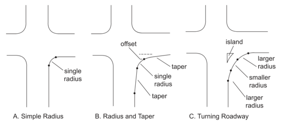
Source: Adapted from A Policy on the Geometric Design of Streets and Highways, AASHTO 2004
Simple Curb Radius
Pavement corner design at simple intersections is controlled by the following factors:
- Turning path of the design vehicle: Designs allow the design vehicle to make lane-to-lane maneuvers without encroaching on adjacent lanes on approaching leg.
- Appropriate level of encroachment by the control vehicle: The control vehicle should not affect the geometry or pavement corner radius of the intersection where possible. Different levels of encroachment are discussed in the previous section.
- Effective corner radius: The cross section of each intersecting roadway influences the turning ability of a design vehicle. For example, on roadways with wide shoulders, bicycle facilities, and/or on-street parking, the effective turning radius will be larger than on a roadway without these elements, making smaller corner radii more feasible as shown in Figure 6-25.
Figure 6-25: Effective Corner Radius

Source: MassDOT
Pavement corner needs for the turning design vehicles should be checked using swept path software. See Table 6-2 for common pavement radii for various design vehicles. Skewed intersections require larger radii than perpendicular intersections. Combinations of curves and tapers or turning roadways may be appropriate in these situations.
Curve and Taper Combinations
The combination of a single radius flanked by tapers can often fit the pavement edge more closely to the design vehicle than a simple radius (with no tapers). This closer fit can be important for large design vehicles where effective pavement width is small. At the majority of all intersections, the pavement corner design is dictated by the right-turn movement. Left turns are seldom a critical factor in corner design except at intersections of two one-way streets, in which case, their corner design is similar to that for right turns at intersections of two-way streets. The method for pavement corner design can vary as shown in Figure 6-24 and described below:
- Simple pavement radius: In most settings, a single radius is the preferred design for the pavement corner. A single radius sized for the design vehicle will control motor vehicle speeds, minimize the crosswalk distance and intersection footprint, and is simpler to design and construct.
- Compound curves or combinations of curves and tapers: Where encroachment by the design vehicle into adjacent lanes must be avoided or where the angle of turn is greater than 90 degrees, compound curves can define the pavement corner edge. Combinations of tapers with a single curve that closely fit the right rear-wheel vehicle track are generally acceptable. Combinations of curves and tapers are typically reserved for high speed, rural applications.
- Turning roadways: A separate right-turn lane, usually delineated by a channelization island may be appropriate where right-turn volumes are large, or where the design vehicle has a wide turning swept path, or where the turn angle is less than 90 degrees. See the section “Channelization Islands” for further guidance.
Figure 6-24 above illustrates design elements for curve and taper combinations that permit various design vehicles to turn, without any encroachment, from a single approach lane into a single departure lane. Table 6-3 provides radius, offset, and taper values for various design vehicles and turn angles.
Table 6-3: Curve and Taper Corner Design Elements
| Angle of Turn (Degrees) | Design Vehicle | Radius (R, feet) | Offset (OS feet) | Taper Length (T, feet) |
|---|---|---|---|---|
| 75 | P | 25 | 2 | 20 |
| SU | 45 | 2 | 20 | |
| WB-62 | 145 | 4 | 80 | |
| 90 | P | 20 | 2.5 | 25 |
| SU | 40 | 2.0 | 20 | |
| WB-62 | 120 | 4.5 | 135 | |
| 105 | P | 20 | 2.5 | - |
| SU | 35 | 3.0 | - | |
| WB-62 | 115 | 3.0 | 45 | |
| 120 | P | 20 | 2.0 | - |
| SU | 30 | 3.0 | - | |
| WB-62 | 100 | 5.0 | 75 | |
| 150 | P | 18 | 2.0 | 20 |
| SU | 30 | 4.0 | 32 | |
| WB-62 | 60 | 10.0 | 100 |
Corner Truck Aprons
A truck apron (Figure 6-26) is a load bearing, traversable surface, typically concrete, outside of the pavement area intended for trailers of articulated vehicles to leave the traveled way. Corner truck aprons are designed to slow most vehicles with a small mountable curb radius while accommodating the control vehicles with a larger radius at the edge of the roadway. Corner truck aprons are not intended to be mounted by single-unit vehicles like SU-30 and transit vehicles.
Truck aprons should be fronted by mountable curbs (e.g., T100 curb) to discourage smaller vehicles from using them and to avoid abrupt, vertical transitions for trailers. Abrupt edges along truck aprons increase the risk of rolling over and damage to vehicle tires. The truck apron should be separated from sidewalks by vertical curbs. If sidewalks are not present on the perimeter of an intersection, then the back of a truck apron should be consistent with drainage type and roadside elements of the approaching roadway segments.
Designers need to consider the impact of corner truck aprons on people walking. Wide truck aprons will push the pedestrian crossing further from the intersection leading to out of direction pedestrian travel, reduced visibility between drivers and pedestrians, and increased challenges for visually impaired pedestrians.
The designer needs to consider how a corner truck apron will affect the Pedestrian Access Route (PAR) and the wayfinding task for visually impaired pedestrians. Corner truck aprons may move accessible crossings outside of a typical accessible route so additional treatments like locator tones or separation between sidewalk and curb may be needed to help pedestrians identify the crossing and maintain the proper direction while crossing. Routing the PAR across a truck apron is possible but is not desirable because visually impaired pedestrians aren’t expecting grade breaks in the roadway, and it risks pedestrians waiting on the truck apron. Additional guidance on visually impaired wayfinding can be found in NCHRP Research Report 834, Chapter 6.
The following guidance applies to the design of corner truck aprons:
- Dimensions: Width and shape should be determined by swept path vehicle analysis of design and control vehicles. Recommended corner truck apron widths should be between 5 to 15 feet.
- Curb height and slope: Truck aprons should be raised by 2 to 3 inches from the adjacent lanes to deter passenger vehicles from traversing them. The apron surface is typically sloped towards the adjacent lane at a cross slope of 1–2%. At locations with steep topography or roadways with open drainage, the truck apron slope could match the cross slope of the adjacent lane to minimize the roadside drop-off.
- Curbing materials: Place mountable curb at the front of truck apron. Place vertical curb behind truck apron to separate it from the sidewalk. If a sidewalk is not installed on the perimeter of the intersection, the back of the truck apron is dictated by the type of roadway drainage. A closed drainage system requires curbing. With an open drainage system, the back of the truck apron can blend into the shoulder or roadside slope.
- Surface materials: Differentiate the truck apron from the adjacent lanes by texturized and colored concrete. The concrete finish on the aprons should not resemble the texture and color of adjacent sidewalks. Brick or stone pavers are not recommended for truck aprons because they can break loose and are difficult to plow.
Figure 6-26: Mountable Truck Apron

Source: MassDOT
Auxiliary Lanes
Auxiliary lanes can be provided for left-turning vehicles, right-turning vehicles, or through vehicles. Deceleration and taper distances provided below should be accepted as a desirable goal and should be provided for, where practical. However, in urban areas it is sometimes not practical to provide the full length of an auxiliary lane. In such cases, at least part of the deceleration must be accomplished before entering the auxiliary lane. Chapter 9 of the AASHTO Green Book provides more information for the designer.
Left-Turn and Right-Turn Lane Design Elements
Turn lanes remove stopped or slow-moving turning motor vehicles from the stream of through traffic, eliminating the primary cause of rear-end crashes at intersections. The safety benefits of turn lanes increase with the design speed of the road, as they greatly reduce both the incidence and severity of rear-end collisions. Turn lanes also improve capacity by freeing the travel lanes for through traffic only.
The safety and capacity benefits of turn lanes apply to all motorized vehicular traffic. However, turn lanes add to the pedestrian crossing distance and pedestrian crossing time. Right-turn lanes provide increased safety for bicyclists operating in mixed traffic by relocating the conflict point between a right-turning vehicle and a through bicyclist. Without a turn lane, a driver turning right from a stopped position is unlikely to look over their right shoulder for bicyclists overtaking the vehicle. When the conflict is located at the opening of a right-turn lane, bicyclists are unlikely to be overtaking motor vehicles on the right. However, on roadways with on-street bicycle lanes, right turns lanes create a conflict point where motorists enter a right turn lane by crossing a bicycle lane. The additional street width needed for turn lanes may require land taking or removal of on-street parking.
The lengths of left-turn lanes, illustrated in Figure 6-27, are calculated to provide two components: (1) desirable lane change and deceleration distance, over which a driver can change lanes from the adjacent through lane into the left-turn lane and decelerate to the back of queue, and (2) storage distance. Table 6-4 shows the desirable distance to allow lane changes and deceleration. The storage length varies depending on the traffic control of the left-turn lane. For unsignalized left-turn movements, Table 6-5 shows storage length as a function of opposing through volume, assuming an 85th percentile critical gap, a vehicle length of 25 feet, and a 0.5% probability of overflow. Equations for calculating lengths based on different critical gaps, overflow probabilities, and vehicle lengths can be found in Chapter 9 of the AASHTO Green Book. Queuing estimates for signalized left-turn movements are provided in the Highway Capacity Manual.
Figure 6-27: Components of a Deceleration Lane
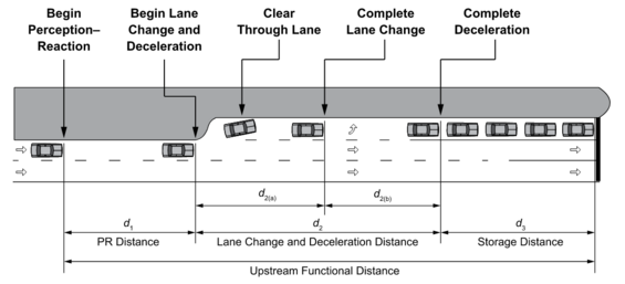
Where:
d1 = distance traveled while driver recognizes upcoming turn lane and prepares for the left-turn maneuver
d2(a) = distance traveled while decelerating and changing lanes from the through lane into the turn lane
d2(b) = distance traveled during deceleration after lane change
d3 = distance provided for the storage of the queue of stopped vehicles waiting to turn
Source: A Policy on Geometric Design of Highways and Streets, AASHTO 2018, 7th Edition, Figure 9-32
Table 6-4: Desirable Lane Change and Deceleration Distance by Speed
| Speed (mph) | Lane Change and Deceleration Distance (ft) |
|---|---|
| 20 | 70 |
| 25 | 105 |
| 30 | 150 |
| 35 | 205 |
| 40 | 265 |
| 45 | 340 |
| 50 | 415 |
| 55 | 505 |
| 60 | 600 |
| 65 | 700 |
| 70 | 815 |
Source: A Policy on Geometric Design of Highways and Streets, AASHTO 2018, 7th Edition, Table 9-20
Table 6-5: Calculated Storage Length by Left-Turn Volume and Opposing Volume
| Left-Turn Volume (veh/h) | Opposing Volume = 200 veh/h | Opposing Volume = 400 veh/h | Opposing Volume = 600 veh/h | Opposing Volume = 800 veh/h | Opposing Volume = 100 veh/h |
|---|---|---|---|---|---|
| 40 | 50 | 50 | 50 | 50 | 50 |
| 60 | 50 | 50 | 50 | 50 | 50 |
| 80 | 50 | 50 | 50 | 50 | 75 |
| 100 | 50 | 50 | 50 | 75 | 75 |
| 120 | 50 | 50 | 75 | 75 | 100 |
| 140 | 50 | 50 | 75 | 100 | 125 |
| 160 | 50 | 75 | 75 | 100 | 150 |
| 180 | 50 | 50 | 75 | 125 | 150 |
| 200 | 50 | 75 | 100 | 125 | 200 |
| 220 | 75 | 75 | 100 | 150 | 225 |
| 240 | 75 | 75 | 125 | 150 | 275 |
| 260 | 75 | 100 | 125 | 175 | 325 |
| 280 | 75 | 100 | 125 | 200 | 400 |
| 300 | 75 | 100 | 150 | 225 | 525 |
Source: A Policy on Geometric Design of Highways and Streets, AASHTO 2018, 7th Edition, Table 9-21
The length of taper required to form the left-turn lane varies with design speed. On high-speed highways, it is common to use a taper rate between 8:1 and 15:1. This is included as a portion of the lane change and deceleration distance described previously.
Volume criteria for considering installation of left-turn lanes are summarized in Figure 6-28, Figure 6-29, and Figure 6-30. The thresholds are intended to communicate conditions where turn lanes may be desirable, rather than a strict requirement. These criteria are based on a combination of left-turning motor vehicle volumes plus opposing through motor vehicle volumes at unsignalized locations.
Figure 6-28: Criteria for Left-Turn Lanes in Urban Areas
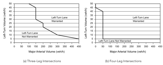
Source: A Policy on Geometric Design of Highways and Streets, AASHTO 2018, 7th Edition, Figure 9-35
Figure 6-29: Criteria for Left-Turn Lanes in Rural Areas (2 Lane Highway)
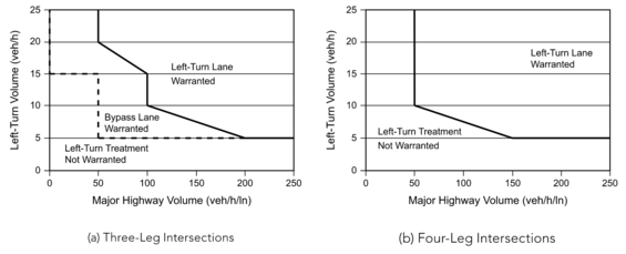
Source: A Policy on Geometric Design of Highways and Streets, AASHTO 2018, 7th Edition, Figure 9-36
Figure 6-30: Criteria for Left-Turn Lanes in Rural Areas (4 Lane Highway)
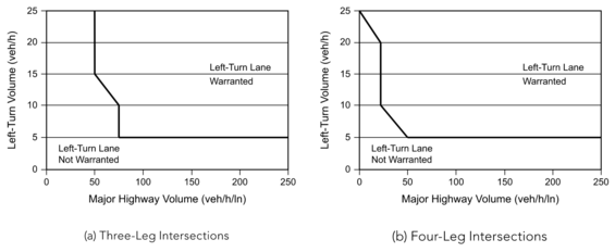
Source: A Policy on Geometric Design of Highways and Streets, AASHTO 2018, 7th Edition, Figure 9-37
Left-turn lanes may yield large benefits in safety and user convenience and may be desirable in many situations with volumes below those stated. These include to destinations of special interest (shopping, major institutions, etc.) or for locations with marginal sight distance on the main road or a consistent occurrence of rear-end crashes. However, provisions for left-turn lanes must be balanced against the need to provide safe, high-comfort facilities with physical separation for people biking and walking through the intersection.
Where there is a need for multiple, closely spaced left-turn lanes (due to driveways or small blocks), it may be advisable to designate a continuous center lane as a “two-way left-turn lane” (TWLTL) as discussed in Chapter 5 and Chapter 15.
Auxiliary Through Lane Design Elements
Short segments of additional through lane (widening a street through a signalized intersection) can be an effective way of increasing intersection capacity at relatively “isolated” intersections. For example, in rural areas and in settled areas with a minimum of about one mile spacing between signalized intersections.
Where through lanes are provided, motorists approaching the intersection arrange themselves into two lanes of traffic and merge back to a single lane of traffic on the departure side of the intersection. Merging under acceleration (i.e., on the departure side of the intersection) works well, since gaps (spaces between motor vehicles) are increasing as vehicles accelerate, leaving numerous opportunities to merge as the traffic stream leaves the intersection. Design elements for auxiliary through lanes are illustrated in Figure 6-31 and their values summarized in Table 6-6.
Figure 6-31: Auxiliary Through Lane Design Guidelines

Source: A Policy on Geometric Design of Highways and Streets, AASHTO 2004
Table 6-6: Auxiliary Through Lane Design Guidelines
| Design Speed (mph) | Lane Width (feet) | Taper Length (T, feet)1 | Length of Lane (L, feet) |
|---|---|---|---|
| 15-25 | 10 | WS2/60 | See Note 2 |
| 30-35 | 10 | WS2/60 | See Note 2 |
| 40 | 10-11 | WS2/60 | See Note 2 |
| 45 | 10-11 | WS | See Note 2 |
| 50 | 11-12 | WS | See Note 2 |
| 55 | 11-12 | WS | See Note 2 |
| 60 | 12 | WS | See Note 2 |
Note 1 W is the lateral shift required to form the additional through lane.
Note 2 L should be based on anticipated queue derived from intersection operations analysis.
Source: A Policy on Geometric Design of Highways and Streets, AASHTO 2004
Channelization Islands
Channelization is the practice of separating movements from the primary traffic stream to improve intersection efficiency. Channelization is often reserved for high turning volumes where maintaining a parallel turn lane would significantly impact operations. Channelization islands are used to:
- Delineate the area in which motor vehicles can operate
- Reduce the area of motor vehicle conflict
- Bring motor vehicle merging into a safer (smaller) angle of merge
- Provide pedestrian refuge
Ideally, channelization islands are raised above pavement level, typically to curb heights between 3 and 6 inches. Raised islands have the ability to serve as a pedestrian refuge if sized appropriately. Less preferably, they may be flush with the pavement level; however, flush islands cannot provide pedestrian refuge. Both raised and flush islands may be constructed of a variety of materials, including conventionally finished concrete, scored concrete, or rigid pavers of various types. Differentiation of surface type or elevation of the pedestrian path through an island provides guidance to pedestrians who are blind or have low vision. Some general criteria for the dimensions of channelization islands include:
- Triangular islands should be a minimum of 50 square feet in surface area in urban areas and 100 square feet in surface area in rural areas with one side at least 15 feet in length.
- Linear islands should be at least 2 feet wide. If they contain signs, they should be at least 4 feet wide. The minimum length of linear islands in the direction of motor vehicle travel should be 25 feet.
- Channelization islands should contain at-grade passages for bicyclists and pedestrians and should generally be placed to avoid impeding bicycle movement, whether or not bicycle lanes are present. If a channelization island intersects a pedestrian crosswalk or shared-use path and is intended to be used as a pedestrian refuge, they must have the following minimum dimensions to meet PROWAG requirements:
- They must be at least 7 feet wide in the direction of pedestrian travel to provide space for 2-foot-wide detectable warning surfaces with a 2-foot minimum gap between them. The detectable warning surfaces are typically set at the back of curbs, which are typically 6 inches wide on either side.
- They must provide a clear width of 5 feet measured perpendicular to the direction of pedestrian travel. If they intersect a shared-use path, they shall be wide enough to provide a clear width greater than 5 feet or the width of the connecting path.
- They must have a maximum design slope of 1.5%.
- The edges of channelization islands should be offset from the travel lanes to guide drivers smoothly into the desired path. Typically, a 2-foot offset is appropriate.
Typical arrangements and applications of channelization are shown in Figure 6-32.
Figure 6-32: Channelization Islands
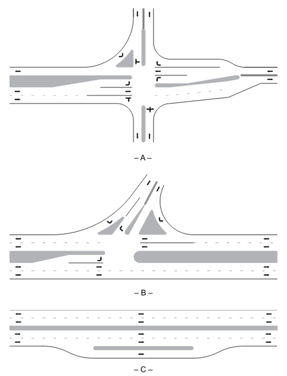
Source: A Policy on Geometric Design of Highways and Streets, AASHTO 2018, 7th Edition, Figure 9-22
Right-Turn Channelization Islands
A right-turn channelization island is the raised, typically concrete, island separating right-turning vehicles from the primary traffic flow.
Right-turn channelization is most often designed as a flared approach intended to stop or yield to the receiving lane or as a bypass that merges with the receiving lane. The bypass design has a higher capacity but may be challenging for pedestrians to cross if uncontrolled. The geometric design needs to match the intended control with the receiving lane.
Right-turn channelization islands can benefit pedestrians crossing the affected approaches by providing an interim refuge in the crosswalk. This refuge permits pedestrians to devote full attention to crossing the right-turn lane without needing to also cross the rest of the street in the same movement. From the channelization island, pedestrians can then proceed across the through lanes of traffic without the complicating factor of crossing the right-turn movement. To comply with PROWAG, crosswalks at multilane channelized turn lanes shall provide one or more of the following treatments: a pedestrian signal, a pedestrian hybrid beacon (PHB), a pedestrian actuated rectangular rapid flashing beacon (RRFB), or a raised crossing.
Figure 6-33 shows two different entry angle and island designs:
- On the left, the isosceles shape of the triangle island results in a flat entry angle, which may be appropriate for channelized right turns without pedestrian facilities and with yield control, or no control and an acceleration lane.
- On the right, the entry angle and island provides a nearly perpendicular angle to the downstream roadway, which promotes good visibility to conflicting vehicles and pedestrians and increases the likelihood of yielding to crossing pedestrians.
In general, designers should design right-turn channelization islands to promote slow speeds through the turn, minimize the need for drivers to turn their heads far to the left, and to provide the pedestrian crossing location before the driver’s downstream yield point.
Figure 6-33: Impact of Entry Angle and Island Shape on Speed and Visibility
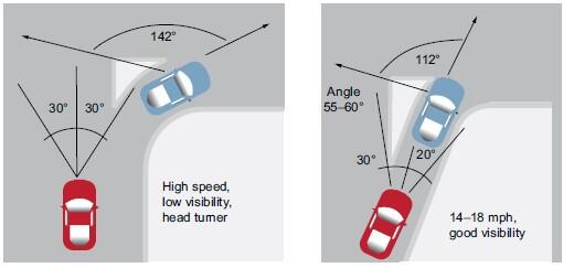
Source: FHWA Ped Safe via A Policy on Geometric Design of Highways and Streets, AASHTO 2018, 7th Edition, Figure 9-19
The design of right-turn channelization islands warrants close attention by designers to ensure that the needs of people who are blind or have low vision are adequately met. For more information, refer to NCHRP Research Report 834, Crossing Solutions at Roundabouts and Channelized Turn Lanes for Pedestrians with Vision Disabilities, A Guidebook. The designer needs to consider potential safety tradeoffs of implementing channelization islands. An island in the clear zone may be struck by passing motorists, cyclists, and road maintenance vehicles like streetsweepers and snowplows. Channelization islands should be set back two feet from the edge of travel lane to accommodate errant road users and snowplow blades. Small channelization islands are difficult to see and should be a minimum of 50 square feet. Minimum design details are shown in Figure 6-34.
Figure 6-34: Minimum Design Detail of Channelized Islands

Source: Adapted from A Policy on Geometric Design of Highways and Streets, AASHTO 2018, 7th Edition, Figure 9-24
Divisional Islands
Divisional islands, shown in Figure 6-35, are useful in dividing opposing directions of traffic flow at intersections on curves, or with skewed angles of approach. In such instances, they can improve the safety and convenience for approaching motorists. Although superficially similar to medians, divisional islands differ from them in their short length and relatively narrow width and are discussed further later in this chapter and in Chapter 16. On curved roadways, it can be beneficial to extend the divisional island to a tangent section to improve the visibility of the leading edge of the island. At roundabouts, divisional islands are often called splitter islands.
Figure 6-35: Alignment of Divisional Islands at Intersections
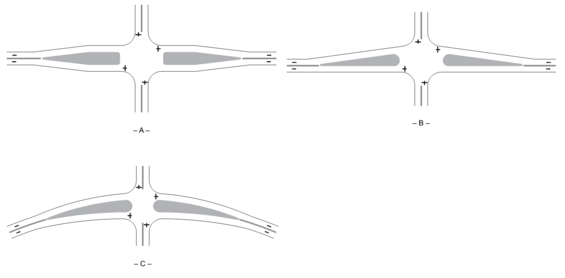
Source: A Policy on Geometric Design of Highways and Streets, AASHTO 2018, 7th Edition, Figure 9-23
Left-Turn Lane Delineator Islands
The left-turn delineator island resembles a short section of median island, with triangular striping to guide traffic around it. At the intersection end of the island, it is narrowed to provide storage for left-turning motor vehicles and bicycles. Where the island is intended to be used for pedestrian refuge, it should be no less than 6 feet wide in the refuge area.
On undivided streets, the left-turn lane delineator island is used to form the left-turn lane. At its upstream nose (i.e., on the approach to the intersection), the island and associated striping shifts the through traffic lane to the right, creating room for the taper and left-turn lane.
Intersection Median Openings
At intersections where one or both streets have divided roadways separated by a median, the design of the median becomes an element in the intersection design. Two factors control the design of the ends of medians at intersections:
- The turning path of motor vehicles and bicycles making a left turn from the minor street into the major street controls the location and shape of the end of the median in the departure leg of the major street
- The left turn from the major street into the minor street determines the location and configuration of the median end on the approach leg of this movement
Right-turn movements are seldom a factor in median opening design. However, the presence of a median may limit the effective pavement width for motor vehicles and bicycles making a right turn. Effective pavement width, as previously discussed, has a large bearing on the corner radius needed for right turns.
An important design element is the length of the median opening, as illustrated in Figure 6-36. Table 6-7 provides above-minimum design dimensions.
Figure 6-36: Median Openings
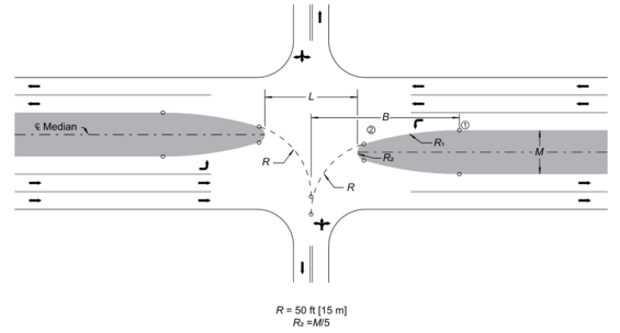
Source: A Policy on the Geometric Design of Highways and Streets, AASHTO 2018, 7th Edition, Figure 9-43
Table 6-7: Median Openings Dimensions (Feet)
| Width of Median, M (ft) | L (R1= 90 ft) | B (R1= 90 ft) | L (R1 = 170 ft) | B (R1 = 170 ft) | L (R1 = 230 ft) | B (R1 = 230 ft) |
|---|---|---|---|---|---|---|
| 20 | 58 | 65 | 66 | 78 | 71 | 90 |
| 30 | 48 | 68 | 57 | 85 | 63 | 101 |
| 40 | 40 | 71 | 50 | 90 | 57 | 109 |
| 50 | - | - | 44 | 95 | 51 | 115 |
| 60 | - | - | - | - | 46 | 122 |
| 70 | - | - | - | - | 41 | 128 |
Source: A Policy on the Geometric Design of Highways and Streets, AASHTO 2018, 7th Edition, Figure 9-43
Mountable Median Openings
Raised medians are useful tools to restrict turning movements where access is not desirable. Where occasional access across a median is needed, such as for emergency vehicles or some control vehicles, providing short sections of mountable median may be appropriate. Designers need to consider the potential tradeoffs of providing mountable median access, including the time benefit to emergency vehicles, alternative access routes for control vehicles, and the potential abuse by unintended users.
Roundabout Geometric Design Elements
Planning and design of roundabouts is detailed in MassDOT’s Guidelines for the Planning and Design of Roundabouts.
Pedestrian Crossings
Pedestrian crossings, whether marked or unmarked, are a critical element of intersection design. Marked pedestrian crossings designate the appropriate path of travel for a pedestrian through the intersection. Several techniques are available to provide optimal pedestrian crossings and for improving crosswalk visibility, as described below.
Crosswalk Pavement Markings
Pavement markings indicate to pedestrians the appropriate route across traffic and remind turning motorists and bicyclists of potential conflicts with pedestrians. The crosswalk edge nearest to the intersection should be aligned with the edge of the sidewalk nearest to the road. Refer to the 2009 Edition of the MUTCD, Figure 3B-19, for acceptable crosswalk markings. When different pavement treatments are used, crosswalks must be bounded by parallel bars (see the Massachusetts Amendments to the 2009 MUTCD for further guidance). At signalized intersections, all crosswalks should be marked. At unsignalized intersections, crosswalks should be marked when they:
- Help orient pedestrians in finding their way across a complex intersection
- Help show pedestrians the shortest route across traffic with the least exposure to motor vehicles and bicycles, and to traffic conflicts
- Help position pedestrians where they can best be seen by on-coming traffic
The decision to mark pedestrian crossings depends on context and is often dependent on the presence of a combination of geometric and traffic control features. At pedestrian crossings in uncontrolled environments with speeds greater than 40 mph, marked pedestrian crossings should only be used with other treatments such as raised medians that provide pedestrian refuge. All crosswalks on the entries and exits of roundabouts should be marked. Crosswalks are typically located one car length back from the yield line or circulating roadway at single-lane roundabouts. For more information, refer to the Manual on Uniform Traffic Control Devices.
Vehicular Stop and Yield Line Placement
Where marked crosswalks are provided across a street with a stop line or with traffic signals, there should be a minimum 4-foot spacing between the outer edge of the crosswalk and the nearest edge of the stop bar. For marked crosswalks at uncontrolled multilane roadways, the yield line should be located 20 to 50 feet in advance of the crosswalk. Stop and yield lines should be dimensioned in accordance with guidelines in the 2009 Edition of the MUTCD and the Massachusetts Amendments to the 2009 MUTCD.
Methods to Reduce Pedestrian Crossing Distance
Marked or unmarked pedestrian crossings should be as short as possible. At all intersections, reducing the time pedestrians are in the crosswalk improves pedestrian safety and motor vehicle and bicycle movement. At signalized intersections, reducing the pedestrian crossing distance can improve capacity and quality of service for both motor vehicles and pedestrians. Curb extensions, use of pedestrian refuge islands, and reduced corner radii are examples of methods to reduce pedestrian crossing distances.
Curb Extensions
Curb extensions shorten the crossing distance, provide additional space at the corner, allow pedestrians to see motor vehicles and be seen by motor vehicle drivers before entering the crosswalk, and keep parking away from crosswalks. Curb extensions are discussed further in Chapter 16.
Pedestrian Refuge Islands
Pedestrian refuge islands can be used to interrupt long pedestrian crossings. These raised areas:
- Allow pedestrians to cross fewer lanes at a time, reducing exposure time
- Allow pedestrians to focus on traffic from only one direction at a time
- Reduce the total distance over which pedestrians are exposed to conflicts with motor vehicles
Islands should not be used to justify signal timing that does not allow pedestrians to complete their crossing in one cycle. Crossing islands are discussed further in Chapter 16.
Reduced Corner Radii
Smaller corner radii reduce the overall crossing distance for pedestrians and reduce speed of turning vehicles-both improving the quality of service for pedestrians. Design of corner radii is detailed in the Pavement Corner Radius section. In contexts where larger trucks are expected to make turns, designing corner radii for design vehicles and using truck aprons to accommodate control vehicles is one way to balance the needs of vehicles and pedestrians.
Improving the Visibility of Pedestrian Crossings
Safe pedestrian crossing is dependent on awareness by motorists of the pedestrian. Methods to improve the visibility of pedestrians, in addition to curb extensions, sometimes include raised crosswalks, flashing beacons, and street lighting at mid-block locations as discussed further in Chapter 16.
Locating Pedestrian Push Buttons
Pedestrian signal push buttons are used to initiate a pedestrian crossing phase at traffic signals. Where needed, pedestrian push buttons should be located to meet the following criteria in conformance with PROWAG:
- Push buttons must be no more than 5 feet from the side of the curb ramp run or the edge of the farthest associated crosswalk line from the center of the intersection
- Push buttons must be between 1.5 and 10 feet from the edge of the curb or pavement
- When two push buttons are located on the same corner, they must be at least 10 feet apart
- The face of the push button must be parallel to the direction of the associated crosswalk
Additional push button location considerations include:
- The closest push button to a crosswalk should call the pedestrian signal for that crosswalk
- Push buttons should be placed in locations that are easy to reach, at a mounting height of approximately 3.5 feet (but no more than 4 feet) above the sidewalk, facing the sidewalk, clearly in line with the direction of travel, and with at least a 48” by 48” clear, level landing centered on the call button
Pedestrian Crossing Prohibitions
Prohibiting pedestrian crossing should be considered only in very limited circumstances, for example:
- Where visibility (for pedestrians, motorists, or bicyclists) is obstructed and the obstruction cannot be reasonably removed, and where all-way stop control, signalization, or a roundabout is not an option
- Where it is desirable to consolidate legal crossings, such as on an arterial street with multiple offset or “T” intersections
Crosswalks at “T” and offset intersections should not be closed unless there is another crossing within 45 feet of the closed crosswalk. This corresponds to a total out-of-distance travel of 90 feet for a pedestrian, or a delay of approximately 30 seconds.
All closed crossings must comply with PROWAG requirements to communicate the presence of the closed crossing to all users, including pedestrians who are blind or have low vision. Where pedestrian crossing is prohibited, curb ramps or blended transitions shall not be provided and the pedestrian circulation path shall be either (a) separated from the roadway with landscaping or other non-prepared surface, or (b) separated from the roadway by a detectable vertical edge treatment with a bottom edge 15 inches maximum above the pedestrian circulation path.
Pedestrian Curb Ramps
Several configurations of pedestrian curb ramps are described in the following sections. Designs for these ramps are provided in MassDOT’s Construction Standard Details.
Two types of ramp configurations are preferred—perpendicular ramps and parallel ramps. The first has a ramp leading at right angles from the sidewalk into a crosswalk, while the second has a ramp leading into a landing that is flush with the street surface. A third type, a diagonal or apex ramp, is discouraged but permissible for specific intersection conditions as described below. There are other types of curb ramps that may be appropriate for a particular location. Refer to the MassDOT Construction Standard Details for the latest standard drawings, and additional information in Engineering Directive E-12-005.
Perpendicular
Whenever possible, 521 CMR requires that a pedestrian curb ramp is oriented so that the slope of the ramp is in line with the crosswalk and perpendicular to the curb. Where conditions are not constrained, the designer should locate the ramp so that both conditions can be met. A level landing is required for each approach at the sidewalk and street level.
Parallel
Parallel curb ramps are used where there is insufficient available space to permit the installation of a perpendicular ramp and a landing. A minimum 5-foot-level landing is necessary at the bottom between the two transition ramps.
Apex
Apex curb ramps are single perpendicular pedestrian curb ramps located at the apex of the corner. Apex ramps are only permitted under specific conditions in the Massachusetts Architectural Access Board regulations, 521 CMR. When using apex curb ramps, there must be a 4-foot level landing at the base (street) level of the ramp that is within the marked crosswalk.
Bicycle Lanes at Intersections
On streets with bicycle lanes, the design of bicycle lanes at intersections should address the need to accommodate numerous turning movements by both motorists and bicyclists, often with limited available space. Design of separated bicycle lanes at intersections is detailed in MassDOT’s Separated Bike Lane Planning & Design Guide, Chapter 4, with additional considerations in Chapter 5 and Chapter 6. Refer to NACTO’s Urban Bikeway Design Guide for additional guidance on elements such as bike boxes, two-stage turn queue boxes, and bike lane markings approaching and through intersections.
6.8 Other Considerations
Several other considerations important for intersection design are described in the following sections.
Intersection Sight Triangles
The intersection sight triangle is a triangular-shaped zone that is sufficiently clear of visual obstructions to permit drivers entering the intersection to detect any hazards or conflicts and react accordingly. Intersection sight distance and sight triangles are discussed further in Chapter 3.
Intersection Spacing
A primary purpose of intersection spacing guidelines is to balance the need for street connectivity for all modes with the desire to minimize conflicts between adjacent intersections. Examples of such conflicts are queues of motor vehicles extending from one intersection through an adjacent intersection or intersection spacing that precludes the possibility of traffic signal progression between signalized intersections. On arterials, intersection spacing requirements are intended to minimize the “friction” arising from signal control and turning movements at intersections. Intersection spacing can also influence the pedestrian connectivity due to crossing opportunities being provided principally at intersections.
Spacing Between Public Street Intersections
Guidelines for spacing between public streets are given in Table 6-8 and illustrated in Figure 6-37. Intersection spacing should consider the area type, surrounding network, walkability and access needs, and target speed.
Figure 6-37: Intersection Spacing Diagram

Source: Adapted from Congress for the New Urbanism (CNU), AASHTO 2005
Table 6-8: Intersection Spacing Guidelines
| Design Speed (mph) | Intersection Spacing (ft) | Offset Intersection Spacing (ft) |
|---|---|---|
| 15-30 | 200 | 50 |
| 35-40 | 250 | 75 |
| 45-50 | 350 | 150 |
| 50 + | 500 | 500 |
Source: Adapted from Congress for the New Urbanism (CNU), AASHTO 2005
In developed areas, often intersection spacing is not a controllable element of intersection design and the spacing is “given” as a fixed condition. In such circumstances, spacing guidelines are not applicable. However, in many situations, particularly involving areas of new development, intersection spacing is an important part of the context and should be considered.
Spacing between Signalized Intersections
Frequently, criteria for the desirable spacing of signalized intersections are confused with that for spacing of all intersections, whether signalized or not. Good signal progression in both directions simultaneously requires signalized intersections to be spaced at regular intervals. However, signalized intersections, spaced for good signal progression, can be combined with unsignalized intersections, yielding overall intersection spacing with small blocks (ideally around 200 feet) appropriate for urban settings.
Good connectivity to the signalized intersections along the major street can be assured with a well-connected network of local and collector streets parallel to the major street. With such a network in place, turning movements can be made at all locations, signalized and unsignalized, during non-peak hours. During peak hours, motorists and bicyclists wanting to enter or cross the major street can choose to use the signalized intersections.
Spacing between Roundabouts
Criteria for spacing between roundabouts is dependent primarily on queuing needs between intersections. Intersection spacing between roundabouts can often be less than between signalized intersections because of shorter queuing needs and not needing to provide progression. Further detail can be found in MassDOT’s Guidelines for the Planning and Design of Roundabouts.
Transit Stop Considerations
From the point of view of bus operations, it is desirable to have bus stops located near intersections for two reasons: (1) intersections provide crossing opportunities to serve bus stops on both sides of the street, and (2) intersections provide direct access from both the street carrying the bus route and from the intersecting streets. The design of boarding and alighting areas must meet PROWAG requirements, including connection to existing pedestrian circulation paths such as sidewalks and shared-use paths.
With respect to intersections, bus and other transit stops are most commonly either:
- Near-side, located on the approach leg of the intersection; or,
- Far-side, located on the departure leg of the intersection.
Bus and other transit stops at intersections, while advantageous for bus service, create challenges for other users:
- If the bus stop is in its own lane (typically an extension of parking lanes toward the interior of the block), it must reenter the traffic stream after completing a stop. If, on the other hand, the bus stops in a lane of motor vehicle or bicycle traffic, it blocks that lane while the bus is stopped.
- At far-side stops, a stopped bus in the travel lane may cause following vehicles to queue through the intersection. A bus stop in its own lane allows motor vehicles and bicycles departing the intersection to bypass the stopped bus.
- At near-side stops located immediately upstream of an unsignalized pedestrian crosswalk, a bus stopped next to an active traffic lane can block the visibility between a motor vehicle and a crossing pedestrian.
- At near-side stops, where the stopped bus is outside the traffic stream, the reentry of the bus into the traffic stream is likely to occur at a pedestrian crosswalk, which presents a potential conflict between buses and pedestrians.
- Bus stops and accessible on-street parking often compete for the location nearest the intersection. The locations of both should be resolved with input from the local disability commission, regional independent living center, and transit agency.
The challenges associated with bus stops at intersections are addressed through the following design guidelines:
- Parking should be restricted for a distance of 60 feet from the beginning of the pavement corner radius. The designated bus loading area should not extend closer than 20 feet to the pavement corner radius. These dimensions apply to both near-side and far-side bus stops.
- Far-side bus stops are generally preferable to near-side stops.
- It is generally desirable to allow buses to stop in the travel lane. Bus pullouts, under some circumstances, may be appropriate at intersection areas. However, the drawback of pullouts—difficulty for the bus in reentering the traffic stream—can be problematic near intersections. Pullouts are more likely to be acceptable at far-side stops, where the exiting bus vehicle is more likely to encounter acceptable gaps in the traffic stream, compared to a near-side stop on the approach leg of the intersection.
Refer to the MBTA’s Bus Stop Planning and Design Guide and NACTO’s Transit Street Design Guide for additional guidance. The design of pedestrian and bicycle connections, bus bays, and on-street parking requires additional focus around intermodal facilities such as commuter rail, subway, park & ride, and light-rail stations. Design of these facilities is overviewed in Chapter 12.
Mid-Block Path Crossings
At intersections, shared-use paths (for pedestrians, bicyclists, and other non-motorized users) are accommodated as intersection crosswalks, as described in the Pedestrian Curb Ramps Section. Where paths cross streets at locations other than at intersections, they should conform to the following guidelines for “mid-block” crossings (the 2009 Edition of the MUTCD provides further guidance on signing and markings):
- Mid-block path crossings should be used only where needed. Factors likely to produce this need are existing route of paths, availability of right-of-way for path extensions, distance to alternate crossing locations at intersections, and topography.
- Mid-block path crossings should be installed only where stopping sight distance is fully adequate for vehicular traffic on the street being crossed.
- Mid-block path crossings should provide adequate sight distance for pedestrians, bicycles, and other users of the path.
- Where mid-block path crossings exceed 60 feet in length, a median island should be considered. Median islands provide the dual benefit of providing a refuge for crossing path users, reducing the size of gap in traffic needed to cross the street safely, and may help alert approaching motorists and bicyclists to the presence of the crossing.
- Median islands should be at least 7 feet wide in the direction of bicycle and pedestrian travel to accommodate the length of a typical adult bicycle and to meet PROWAG requirements, with larger dimensions preferred to serve a wider range of bicycle configurations.
- Trees along the roadside at the path crossing, and in larger medians, can call attention of on-coming motorists to the presence of the trail crossing. However, trees and other landscaping should not be allowed to infringe on the sight distance of pedestrians, bicyclists, or motorists in the vicinity of the crossing.
- All median or channelizing islands shall have pedestrian curb ramps or at-grade cut-throughs, in conformance with 521 CMR and PROWAG. At-grade cut-throughs should be sloped gently (maximum of 2% in the build condition and preferably 1.5% in design) to allow drainage and meet PROWAG requirements.
- On multilane arterial streets, pedestrian push button-actuated traffic signals may be appropriate. When installed, such signal installations should have a supplementary push button at the median, as well as at either curb. Design details for push buttons are detailed in the “Locating Pedestrian Push Buttons” section under 6.7 Geometric Design Elements.
- On-street parking should be removed for a distance (typically 40 to 60 feet) adequate to assure sight distance for path users waiting on the curb. An alternative treatment where parking is present is to provide a curb extension, typically 6 feet deep for a parking lane that is 7 to 8 feet wide. Curb extensions reduce or eliminate the need for removing parking and decrease the crossing distance for the path.
- Crosswalks should be marked. The use of high visibility crosswalk markings, advanced signing, curb extensions, rectangular rapid-flashing beacons, and pedestrian hybrid beacons should be considered as outlined in Table 1 of FHWA’s Guide for Improving Pedestrian Safety at Uncontrolled Crossing Locations.
Railroad-Highway Grade Crossings
The following guidelines affect the horizontal alignment of streets at a railroad-highway grade crossing:
- Crossings should be avoided on both highway and railroad curves. Railroad curves present a problem of superelevated track crossing the roadway. A curve on the crossing highway prevents any superelevation on the highway, resulting in an awkward or unsafe curve.
- The highway should intersect tracks as near as possible to 90 degrees.
- Ideally, there should not be nearby intersections with streets or driveways. Where it is not possible to provide sufficient distance between the crossing and nearby intersections, traffic signals at the nearby intersection can be interconnected with the grade crossing signal to enable vehicles to clear the grade crossing as a train approaches.
- The crossing should be wide enough to permit bicyclists to cross the tracks at right angles, while staying in their traffic lane.
The following guidelines apply to the vertical alignment of streets at railroad highway grade crossings:
- The street surface should be at the same plane as the cross-slope of the top of the rails (level for tangent rail and adopting the grade of superelevated rail for 2 feet outside either rail. Beyond this point (i.e., 2 feet from outside edge of rail), the grade should not be more than 1% greater than the grade across the tracks.
- Vertical curves should be used to make the transition from the street grade to the rail cross-slope plane described above.
Traffic control devices for railroad-highway grade crossings range from passive (signs, pavement markings) to active (flashing light signals) to restrictive (automatic gates). Consult the 2009 Edition of the MUTCD for detailed criteria for the design and operation of these devices. At crossings protected by active signals or gates, the sight distance requirement is determined by the design speed of the crossing street (see Chapter 3).
At crossings without train-activated warning devices, the sight distance must allow the driver or bicyclist to observe the approaching train at sufficient distance to permit stopping prior to reaching the crossing. The distance needed for this case depends on the speed of the vehicle and the speed of the train. Detailed sight distances are given for the WB-62 design vehicle in the AASHTO Green Book.
Where public sidewalks cross rail systems at-grade, the surface of the continuous passage shall be level and flush with the rail top at the outer edge and between the rails. As required by 521 CMR and PROWAG, the horizontal gap on the inner edge of each rail shall be the minimum necessary to allow passage of wheel flanges and shall not exceed 2.5 inches. Where tracks cross a sidewalk, a 24-inch-wide detectable warning surface complying with 521 CMR shall be placed on both sides of the tracks across the entire width of the sidewalk, at a sufficient distance from the tracks to allow clearance for the widest vehicle using those tracks. Where multiple tracks are part of the same level crossing, detectable warnings should be placed outside the outermost track and not within the sets of tracks.
Traffic Diversion Measures
Traffic diversion measures are intended to reduce traffic on certain roadways and intentionally redirect traffic movements onto other roadways. Traffic diversion measures can be part of a more comprehensive plan to create low-volume, lower-speed corridors that are comfortable for biking without dedicated or separated bicycle facilities. Traffic diversion measures are not a substitute for speed management measures where lower speeds are the primary goal.
Traffic diversion measures fall into two categories:
- Movements physically restricted by street design features
- Regulatory restrictions, conveyed primarily through signs
Restriction of Vehicle Movements through Street Design
Several design measures are available to restrict specific movements at an intersection. For example, a segment of median extending across an intersection limits turning movements, from all approaches, to a right-turn only. Further, a median eliminates the possibility of through trips on the cross street. This type of cross-street access restriction by medians could be appropriate where sight distance is inadequate for safe turning movements at the intersection or where through traffic on the cross street is being discouraged. Other techniques such as the use of channelizing islands for particular movements can be used to restrict traffic movements at intersections. Concerns about emergency response access can be mitigated by using mountable curbs or by placing fire hydrants at accessible locations near design elements.
On local streets, the diagonal street closure, shown in Figure 6-38, prevents through movements on both of the intersecting streets, but allows either a right or left turn from all approaches. Diagonal through movement closure may be appropriate to discourage cut-through trips in neighborhood districts with a dense, well-connected network of streets. Diagonal street closures should be designed to maintain connectivity for bicycle travel. For further guidance on restricting vehicle movements, refer to NACTO’s Urban Bikeway Design Guide.
Figure 6-38 Diagonal Street Closure
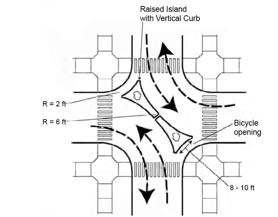
Source: Traffic Calming State of the Practice, ITE 1999
Completely blockading (i.e., completely closing) a street should not be considered as a traffic diversion measure. Street closures should be considered only in instances where such closure is vital for a public purpose (for example, major park or public institution) and then only when an ample, well-connected network remains. Restriction of vehicle movements at town lines is not permitted without the consent of the adjacent community.
Regulatory Measures to Restrict Vehicle Movements
Turn restrictions, on both right turns and left turns, have long been used at intersections to improve pedestrian or traffic flow, and such measures can be used as traffic diversion actions. Restrictions on turning movements (“no left turn” or “no right turn”), are commonly used to expedite traffic flow. Turning movement restrictions can be more efficiently policed than speed or stop control violations. The drawback of traffic diversion measures that rely on regulation is less for turn restrictions than most other types of regulatory action.
The all-way turn restriction, with neither right nor left turns permitted from any approach, is sometimes used at downtown intersections, where large volumes of pedestrians are present on all crosswalks. When used as a traffic diversion measure, an all-way turn restriction has the further impact of redirecting traffic away from areas of special concern and channeling it toward intended routes.
Turn restrictions have value in traffic diversion when used to discourage the use of inappropriate routes. Turn restrictions that apply only during the peak hour, intended to prevent peak hour commuter cut-through traffic in neighborhoods, can also be effective.
Driveways
Driveways are points of access from public streets to private property and are therefore not intersections, as defined in this chapter, although some large volume driveways should be designed as intersections. Guidelines for driveway design and spacing can be found in Chapter 15.
6.9 For Further Information
- AASHTO. A Policy on Geometric Design of Highways and Streets, 2018
- This is generally referred to as the AASHTO Green Book throughout the PDDG.
- AASHTO Guide for the Development of Bicycle Facilities, 5th ed., 2024
- AASHTO Guide for the Planning, Design and Operation of Pedestrian Facilities, 2nd ed., 2021
- Commonwealth of Massachusetts 521 CMR – Rules and Regulations of the Massachusetts Architectural Access Board, Boston, 2018
- Federal Highway Administration (FHWA). Manual on Uniform Traffic Control Devices for Streets and Highways, 2009 Edition
- Institute of Transportation Engineers (ITE), Guidelines for Driveway Design and Location, 1987
- MassDOT Guidelines for the Planning and Design of Roundabouts, 2022
- National Academies of Sciences, Engineering, and Medicine. Highway Capacity Manual 7th Edition: A Guide for Multimodal Mobility Analysis, 2022.
- National Academies of Sciences, Engineering, and Medicine. Guide for Roundabouts, 2023
- NCHRP Research Report 1061: Highway and Street Design Vehicles, An Update (2023)
- United States Access Board, Public Right-of-Way Accessibility Guidelines, 2023