18.1 Introduction
Plans convey physical information so that designers, reviewers, and the public can understand both the existing conditions and the proposed design. Plans also allow a contractor to construct the proposed project and define the right-of-way available or to be acquired. This chapter describes the procedures for developing different types of plans associated with MassDOT projects.
Specifications define the construction methods, materials, method of measurement and basis of payment. The Standard Specifications for Highways and Bridges (along with issued Supplemental Specifications) are used on all MassDOT road and bridge projects; however, project-specific special provisions are often required and prepared to modify the Standard Specifications or to describe unique requirements for specific items or work. This chapter describes the procedures for developing special provisions, describes their format and content, and provides guidance on specific language to be used or avoided.
Estimates of project item quantities and unit bid prices are prepared for project budgeting, to help define project requirements, and to evaluate responses to project advertisements. This chapter also describes estimating procedures for MassDOT projects.
18.2 Construction Plans
All projects must be developed in compliance with the MassDOT Highway Division CAD Standards to ensure consistency between projects. Requirements for base plan (survey) submittals and final construction plan submittals differ and are described below.
Base Plans
Base plans show all existing man-made and natural features located within the proposed project limits. Base plans also show state, county, city, and town layouts, city/town lines, property lines, owners' names, deed references, land court case numbers and land court certificate numbers. Guidance for survey work and the development of base plans can be found in the Field Survey Guidelines and Baseplan Requirements for Survey and Design Consultants.
Final Plans
The final construction plans shall include all drawings and data necessary for proper construction of the proposed project. For guidance on the presentation and format of construction plans, the designer should refer to the full set of Sample Plans, which include:
Boring Logs
Boring logs are required for all projects with a structural component (such as for a bridge, a wall, or a traffic signal mast arm). The MassDOT Bridge Manual requires boring logs to be plotted on the plans. Refer to the MassDOT Bridge Manual for details on boring log requirements for bridge projects. For projects without bridge plans, soil logs are typically shown in the key plan and boring location plan, but may be provided in the specifications, as necessary.
18.3 Decree Plans
MassDOT Highway is required to make decree plans when existing railroad crossings are abolished or altered in conjunction with highway work. MassDOT has jurisdiction for abolitions on all public highways within the state for any alterations on state highways or direct continuations of state highways.
When a new state highway layout crosses a railroad where no crossing previously existed, a decree plan is not required - the layout plans will be sufficient.
A crossing is considered to be altered when:
- An existing bridge has major structural changes to strengthen or improve it;
- An existing highway layout at a grade crossing is widened; or
- The grade crossing is resurfaced or repaired outside the state highway layout (changes to grade crossings within the existing state highway layout are not considered alterations).
Decree plans for alterations must show layouts, takings, major construction and design detail, bridge plans and plans of existing conditions. The plan should extend about 600 feet on either side of the crossing. Decree plans are not a part of the construction plans but a separate set of plans.
The following data must be shown on decree plans:
- Existing Conditions — All existing detail and proposed edges.
- Proposed Surface — The type of surface on pavements, walks, drives, etc. should be identified as "Proposed (kind) Pavement."
18.4 Layout Plans
Layout plans, descriptions, and orders of taking are required to establish highway right of way for all projects which involve land takings. The proposed layouts may result in changes to existing state highway layouts or to existing county, city, or town layouts, or may revise existing limited access provisions.
All proposed layouts must be accurately computed. A complete set of original calculations and a check set of calculations must be submitted. Where a project is in more than one municipality, separate layouts are required. Railroad baselines should be tied to the state highway layout.
Plans shall be prepared in accordance with the MassDOT Highway Division CAD Standards, the Layout Section Standards, and the Layout/Easement Plan Preparation Guidelines. The Layout Section will also provide instructions and a specification package for the plan and written instrument specific to the circumstances of the project.
The below narrative provides a general overview:
- On the Right-of-Way Plans, the designer will furnish the tentative location of the layout line.
- The tentative location is then definitely set and the computations of curves, lengths, bearings, etc., are made. The computed layout data is then shown on the Layout Plans along with the Massachusetts State Plane Coordinates to all angle points, points of curvature, and points of beginning and ending. Deeds, existing state, county, city, and town layouts, survey ties into the Massachusetts State Plane Coordinate system, and other sources of information may be needed to complete the above.
- Layout plans will show proposed layout (location) lines, approximate property lines and sometimes surveyed property lines, corner markers, names of property owners, access and non-access (if limited access highway) points, and the locations of bounds. The plans will indicate existing surface details, such as trees, poles, structures, manholes, curbing, walls, fences, streams, existing streets, etc. The proposed details are not shown.
- The bearings and distances, or radii and lengths of all proposed layout lines are shown in English units, including Massachusetts State Plane Coordinates to all angle points, points of curvature, and the points of beginning and ending. When a record baseline exists in the area of proposed layout or alteration, it shall be shown on the plan to facilitate in determining locus. Ties to this baseline are shown at the beginning of and ending of alteration sections or where instructed by the State Layout Engineer.
Data on the layout plans are to be drawn as described below:
- Layout plans are normally drawn to a scale of either 1” = 20’ or 1” = 40’.
- Where a record baseline exists and is shown, points of curvature, points of tangency and the applicable description "Main Baseline" or "Auxiliary Baseline" will be shown along each baseline.
- The proposed state highway layout line is a heavy, solid line, with bearing, radius and length indicated along the outside of the line. Access provisions are shown inside the layout line.
- The old state highway layout line, where superseded by a revised state highway layout line, is a broken line.
- The state highway layout line is a thin solid line.
- The proposed town or city layout line is a solid line. The bearings, radii and lengths are indicated along the outside of the line.
- The old town or city layout line is a broken line. The date that the existing layout line was made is noted along the line.
- Property lines are shown as broken lines.
- Each parcel of land to be taken must have its parcel number, owner's name, area and length of each course ± distances noted. Registered land must show the parcel number, exact name of owner, the words "Registered Land," Land Court case number, Land Court certificate number, book and page number, the area, and the length of each course. Supplementary plans and traverses must be submitted to the Land Court to conform to Land Court Regulations for the land taken and land remaining. Easement locations taken in connection with the layout will be outlined in black, dashed ink lines marked "Line of Easement."
- Existing state highway layout lines shall be identified with the proper notation, as follows: Layout Lines of December 20, 1995 State Highway Layout/Alteration (L.O. No. 5678).
In accordance with MassDOT practice, parcels are numbered in a manner that will indicate permanent or temporary takings and the nature of the rights taken. Locations where rights of access to or egress from existing ways are taken, but no land taking is involved, will be designated by parcel numbers AT-1, AT-2, etc.
The written instrument for the Layout and Order of Taking will be prepared according to MassDOT practice. Three typewritten copies, double-spaced and carefully checked against the layout tracings, must be submitted. Separate plans and written instruments for advance taking and/or additional easements may be required.
All submissions of tracings to the Department shall be comprised of the original tracings and full-size wash mylar reproductions. Electrostatic mylar plots are unacceptable. The reproductions, to be acceptable to the registers of deeds, must meet the most recent Plan Regulations approved by the State Attorney General.
18.5 Right of Way Plans
When a road, bridge, or corridor owned by the Commonwealth of Massachusetts is affected by a project that is funded through the State Transportation Improvement Program (STIP), MassDOT is responsible for acquiring all needed rights in private and public lands along State owned roadways. The municipalities and Local Public Agencies are responsible for acquiring all needed rights in private and public lands along roads owned by the municipality/Local Public Agency. MassDOT has many professionals dedicated to the acquisition process. Guidance relating to the preparation of right of way plans can be found in the Plan Preparation Guidelines for Consultants Preparing Right of Way Plans.
18.6 Specifications
Construction contracts for bridge and highway improvement projects are prepared by utilizing the current edition of the MassDOT Highway Division Standard Specifications for Highways and Bridges as the base specification for the project, along with the Department’s current interim or Supplemental Specifications to the Standard Specifications for Highways and Bridges (if any have been issued).
The designer should use the standard items specified in the Standard Specifications to the greatest extent practicable, therefore avoiding the need to supplement the construction documents with unique items that are currently not standard. In certain instances, however, projects contain proposed features that are not specified in the Standard Specifications, thereby requiring the development of Special Provisions. The designer should only use a special provision when a standard specification does not exist for a particular contract work item.
Order of Precedence
The Contract Documents prepared for a project take precedence as outlined MassDOT’s Standard Specifications, Division I, Section 5.00, Subsection 5.04: Order of Precedence.
Preparing Specifications
The Standard Specifications are based on a unit price format. Each major item of work is defined and paid for separately at the unit price bid for the work. Payment for most work items is based on the measured quantity of work actually constructed, while some items are paid on a lump sum basis.
The first task in preparing project specifications is to prepare the project estimate showing the unit price items needed to pay for all the project construction. The MassDOT Standard Item List is used for this purpose. New items are written for special work for all non-standard items included on the list.
The next step is to determine if the proposed work requires a Special Provision by:
- Reviewing the work defined on the drawings and comparing it to the Standard Specifications for the particular payment item under consideration. If some part of the required work, such as a material or performance requirement, construction method, or payment provision, is not adequately covered, then the designer should write a Special Provision for this part of the work. The Special Provision should not duplicate Standard Specification language that is not being modified and only describe the changes to the required work. The designer should create a new payment item number by adding a numeric suffix to the Standard Specification payment item that the Special Provision modifies.
- If a Standard Specification for the item does not exist, then the designer should write a Special Provision that includes the scope, construction methods, materials, method of measurement, and basis of payment. The designer should create a new payment item number based on the Standard Specification subsection that most closely relates to the required work.
- When a Special Provision covers the same work under several unit price items, it is not repeated but made applicable to all by including all the item titles in the title of the Special Provision.
Format and Content
Write Special Provisions to contain the following information in the following order:
- Reference
- Content
- Method of Measurement and Basis of Payment
Reference
Reference the Special Provision to the applicable section/subsection of the Standard Specification in the first sentence and thereby tie both Standard and Special Provisions together into a single complete specification. The first sentence should read:
- "The work under this (these) items shall conform to the relevant provisions of Section/Subsection (no. or nos.) of the Standard Specifications and the following:"
This sentence is omitted only in the new specifications that are not supplemental to any section of the Standard Specifications.
Content
The body of the specification contains the scope, material, quality, performance and method instructions, measurement, and payment. It should not duplicate any requirements already adequately covered in the Standard Specifications.
The first sentence should read "The work under this Item shall include…" followed by a brief overview of the particular construction to be specified.
Material and material quality specifications are described next by generic name or manufacturer title. Generic material quality is defined by standard ASTM, AASHTO, or other specifications references. When specifying materials by manufacturer, include three choices whenever possible, and end with "or approved equal." Otherwise, a waiver for the use of proprietary materials is required.
Material and material quality requirements are followed by requirements for construction performance, equipment and methods, such as:
- "place, grade and compact the gravel base…"
- "the concrete base shall be thoroughly cleaned…"
- "… shall be conducted by workmen thoroughly experienced…"
This part of the specification should be written in concise language in start-to-finish order. For example, requirements for preparatory work are written first, followed by principal construction, followed by finishing requirements.
When writing requirements, imperative verbs should be used expressing direct commands, requests, and prohibitions.
Method of Measurement and Basis of Payment
These clauses are the last part of the specification and should not be inserted fully or partially within the body of the Special Provision. If desired to call attention to separate or no separate payment for a particular task within the body of Special Provision, say so, but put a detailed description in the measurement and payment clause. Method of Measurement and Basis of Payment should not be combined into one paragraph; instead, they should be separate clauses in the same manner as the Standard Specifications. The Basis of Payment should be a definitive statement not containing words with undefined criteria such as “to the satisfaction of the Engineer”.
The Standard Specifications describe separately how a particular item of work will be measured for payment and how the measured quantity will be paid for. Special Provisions must use this same format.
Method of Measurement clauses are written:
- "(Item No.) will be measured for payment by the (measurement unit) (follow with the definition of where the measurement will be taken, e.g., from end post to…, on the pavement surface…, etc., when applicable), complete in place.”
Measurements are assumed to be taken in a horizontal plane or vertical plane unless otherwise noted in the measurement clause. The difference can be significant when the work is on a slope and the measurement is linear or an area, such as for pipe, seeding, etc.
Lump sum items do not require a measurement clause.
Basis of Payment clauses are written:
- "(Item No.) will be paid for at the Contract unit price per (measurement unit), which price shall include all labor, materials, equipment and incidental costs required to complete the work."
The payment clause can be written to cover more than one unit price item with the same measurement unit with the words "at the respective Contract unit prices per (measurement unit)."
Do not expand the "all labor, materials…" clause with additional words such as "transporting," cutting," "storage," "cleaning," etc. since these can all be considered covered by the words labor, materials, equipment or incidental costs, or clarified by inclusion in the "no separate payment" sentence.
When payment for a particular part of the work is to be paid for under another item, add the standard sentence:
- "[Work description] will be paid for separately under (Item title), (Item number)."
When the cost of a particular part of the work is to be included in the unit price bid and therefore no separate payment is to be made, but there could be some question of payment since the same or similar work is included in the other items, then include the standard sentence:
- "No separate payment will be made for (work or material description), but all costs in connection therewith shall be included in the Contract unit price bid.” (If the Special Provision is for more than one item, include item title and number reference here.)
This sentence can also be used to call attention to some special or unusual part of the work whose cost is to be included in the unit price.
Redundancy
Redundancy should be avoided. A requirement needs only to be stated once to be binding. Duplication of requirements already adequately covered in the Standard Specifications, in other sections of the Special Provisions, or in the Detail Sheets should be avoided. Notes shown in the Detail Sheets should not replace or duplicate information that is already in, or should be in, the specifications.
Coordination with the Drawings
Terminology
The labels used on the drawings must be consistent with the payment item titles, material names and specification titles used in the technical applications.
For example:
- The plans should not label fill or backfill as structural fill, or gravel, while the specification and payment item is for gravel borrow or processed gravel.
Reference to Information on the Drawings
The term, “as shown on the drawings,” is frequently found in specifications. The term appears to be most often included out of force of habit, usually in the sentence, “as shown on the drawings and as directed by the Engineer.”
This term is not needed since the drawings are as much a part of the Contract Documents as the Specifications and the contractor is responsible for finding the information and does not have to be repeatedly told to do so. The term should be reserved for some unusual type of work where:
- The Specifications and the Drawings need to be studied together to achieve a full understanding of what is required.
- The contractor is given a choice of options in the specifications and the drawings illustrate only one of the choices.
Also, when the term is used, there must be something relevant shown on the drawings. Too often the term is included, but there’s actually nothing relevant on the drawings and the term therefore is not only unnecessary, but erroneous.
Duplication of Notes
Notes shown on the drawings should not replace or duplicate information that is already in, or should be in, the specifications.
Notes should not include:
- Material requirements, such as concrete strength and reinforcing steel strength.
- AASHTO references.
- Performance requirements.
- Measurement and payment statements.
Language
Specifications are precise legal requirements which affect how a contractor will perform the work and how they will determine their costs and bid prices. Item terminology must be uniform, clear in description, and must agree with the plans, detail sheets and estimate. The language, therefore, must be distinct and specific to avoid questions on the intent, requirements, and basis of payment. Specification language must be clearly worded, consistent, specific, and complete. The key to good specification language is to use:
- Only those words that are necessary.
- Words whose meaning can be determined by a quality or quantity criteria.
- Words that are technically correct and not jargon.
Unnecessary or "empty" words – do not add meaning to the specification and should be avoided. These phrases include:
- In order to
- So as to
- To the fact that
- In such a manner as to
Words and phrases must also be technically and legally correct and have only one meaning.
| Language to Avoid | Better Language |
|---|---|
| are to be, may, should | shall |
| his, hers, him, he, she | contractor, agency (not a person) |
| directed by the Engineer | required by the Engineer |
| insure (means insurance) | ensure |
| manner that will not cause | prevent |
| necessary (subject to dispute) | required |
| borne, absorbed, covered | paid |
Words and phrases that have no criteria to define or enforce their meaning should not be used. These include:
- satisfactory, adequate, neatly, suitably, properly
- workmanlike, workmanship
- highest quality, best practices
- to the satisfaction of
- excessive stress
- a manner acceptable to
- pleasing, well-tailored, etc., appearance
- firmly, securely, necessary
Strive to use words that are as specific as possible, yet are general enough to cover all relevant conditions.
| Language to Avoid | Better Language |
|---|---|
| Excavate and dispose of | Remove and dispose of; or Excavate, remove and dispose of |
| …fire alarm apparatus | …fire alarm system equipment |
| …operations on the water mains… | …alterations of the existing water system… |
| damaged by the Contractor due to neglect… | damaged by the Contractor’s operations… |
| …of the applicable item aforementioned in these Special Provisions | of Item (No.)… |
Words used to describe materials and technical terms must not be jargon and must match the words and terms used on the plans and in the payment items. Common examples include:
| Language to Avoid | Better Language |
|---|---|
| Dig, bulldoze | Excavate, trench |
| Main, line | Pipe |
| Blacktop, Bituminous Concrete | Hot Mix Asphalt, HMA |
| Popcorn mix | Open graded friction course |
| Blading, dozing | Grading |
| Gate | Gate Valve |
| Duct | Conduit (single electrical pipe) |
| Conduit | Duct (many electrical pipes in the group) |
| Mill, Micromill | Cold plane |
| Layer | Course (bituminous concrete) |
| Rebar | Reinforcing bars (steel) |
| Masonry, brick | Masonry work, brick work, etc. |
| Thrubolts | Through bolts |
In addition to the use of correct words, phrases and sentences must be worded clearly and correctly. Some frequently used phrases to be avoided include:
- “The Contractor shall be responsible for” – The contractor is responsible for all the contract requirements, thus it is not necessary to state it. This statement is only needed when the task may normally be accomplished by others, but paid for elsewhere, and similar circumstances. Permits are an example.
- “To the satisfaction of the Engineer” – An undeterminable requirement.
- Quotation marks for dimension units should not be used since they can be easily incorrectly typed or lost in printing. The words foot, inch, etc. should always be used and fully spelled out.
- Words or terms that provide an option on the extent that the requirement is to be satisfied such as "may", "if required", "as appropriate", or "if practical".
- Generalities where numbers are really required such as "large", "rapid", "many", "timely", "most", or "close".
- Relative meanings terms such as "easy", "normal", "adequate", or "effective".
Will vs. Shall
- “Will” is a term used to describe an activity performed by MassDOT, e.g., ”Payment will be made…”
- “Shall” is a term used for an activity imposed upon the contractor, e.g., “Work under this item shall include…”
Quantity Detail Sheets
Quantity Detail Sheets are included as part of the contract documents to help potential contractors facilitate their bids on a project. The Detail Sheets are intended to provide a written description of contract items that cannot be sufficiently described by the plans alone; or for descriptions of items on projects that do not have plans. Additionally, if the location of a specific feature to be constructed cannot be located using the plans alone or is otherwise ambiguous, stations and offsets (or other information sufficient to locate the feature) should be included. Figure 18-2 and Figure 18-3 provide examples of Quantity Detail Sheets.
If a project is proposing pavement work and no plan set is intended to be published as part of the Contract, the Quantity Detail Sheets shall include the Pavement Notes for the project.
Other considerations for the Quantity Detail Sheets include:
- Unit costs or other cost estimates are not included in the Quantity Detail Sheets.
- The Quantity Detail Sheets should not use the word “contingency.” Instead, the Quantity Detail Sheets should explain the intended use of the item. (For example, “Item for use to replace existing service boxes found to be broken.”)
- Not every item in the Contract needs to have an entry in the Quantity Detail Sheets. Only items where a summary would help the contractor expedite the preparation of their bids are necessary. (Items for “Field Office”, “Mobilization”, “Schedule of Operations” do not typically require entries in the Quantity Detail Sheets as these are otherwise sufficiently described in the Specifications.)
Figure 18-2: Sample Quantity Detail Sheet (1)
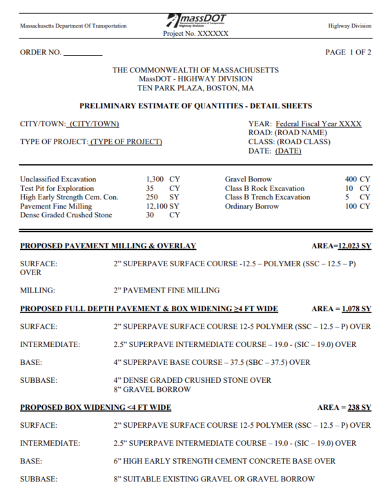
Source: MassDOT
Figure 18‑3: Example Quantity Detail Sheet (2)
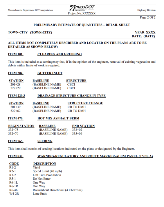
Source: MassDOT
18.7 Estimates
All projects require a preliminary estimate of the quantity and unit bid price for each construction item. Detailed guidance on the preparation of preliminary estimates can be found in the MassDOT Guide to Estimating Highway Projects.
Estimate Structure
The preliminary estimate for each project consists of the following:
- Office Estimate – A list of items necessary for the physical construction of the project. The Designer is responsible for preparing an Office Estimate with estimated quantities and unit prices. When advertised to bidders, the estimated quantity of each item will be made available with the unit prices hidden. Prospective contractors use the quantities along with the published bid documents as the basis for preparing their bid on the project.
- Design Contingency – A value included in a project estimate which is intended to account for the anticipated cost increases as design progresses. The design contingency is highest at planning stages and is reduced to zero at final design once all project elements have been identified and estimated. MassDOT adds design contingency when justified; Designers should not include the contingency in their Office Estimate, but should advise the Project Manager on the requirement and magnitude of a contingency based on perceived risk at each submission.
- Allowance Items – Items that are included to allow the contractor to bill for services, but are not required to be bid on by the contractor. Examples include:
- Traffic Police
- Trainees
- Extra Depth Class A Trench Excavation
- Cofferdam Class B Rock Excavation
- Railroad (RR) Flaggers
- Incentive/Disincentive
- Engineering Services
- Specialty Services
- Equipment Rental
- Construction Engineering – An estimated amount intended to cover MassDOT’s salary costs, inspectional services, QA, and QC testing. Construction Engineering is calculated by MassDOT.
- Construction Contingency – A budget built into every project to provide a funding mechanism for cost increases that may occur during the implementation of the construction contract. Construction Contingency is calculated by MassDOT.
- Utility Force Accounts – When construction of a project requires the relocation of privately-owned utilities, a portion of the costs associated with the relocation are reimbursable. If the utility owner completes their relocation work within the approved schedule, as determined by MassDOT, MassDOT will reimburse the owner 50% (or other partial amount) of the actual costs incurred for the relocation, including costs for temporary (if necessary) and permanent relocations. Municipally-owned utilities will be reimbursed for 100% of the actual costs incurred for the necessary relocation of their facilities. Further details are provided in the Additional Guidance section, below.
- Escalation – Used to forecast the future value of a project based on changes to the cost of labor, materials, and services over time. Escalation is calculated by MassDOT.
Additional Guidance
The following sections provide guidance for Designers to use when preparing the project estimate not otherwise addressed in the MassDOT Guide to Estimating Highway Projects.
Construction Project Estimator (CPE)
Office Estimates for MassDOT projects are required to be developed using the MassDOT Construction Project Estimator (CPE). The CPE helps Designers produce an Office Estimate using computed statistics from previous bids and is updated weekly. Documentation on the CPE is available.
Funding Sources
There are a variety of sources of funding for highway projects. Some funding sources are provided by the Federal government (Federal Aid); some are from funds provided by the Commonwealth (Non-Federal Aid); others are miscellaneous funds that must be identified by the project proponent (non-participating). During project development, the Project Manager will provide the Designer with the proposed funding sources for each project as programmed in the TIP. The estimated quantity of each item must be assigned to a specific funding source in the CPE.
Federal Aid vs. Non-Federal Aid
Federal Aid funding categories generally require a cost share to be provided by the state (such as Surface Transportation Program (STP) funds having 80% of the project funded by FHWA, with the remaining 20% funded by the Commonwealth). The state’s share of funding is calculated automatically when the Office Estimate is loaded into ProjectInfo and does not need to be split out by the Designer.
Work that is not eligible for Federal funds (such as cleaning drainage systems) should be added to an appropriate Non-Federal Aid funding category.
Non-Participating
The terminology “non-participating” refers to items that are not eligible for either Federal or state funds. Items may be identified as non-participating if the work is not necessary to complete the project (such as upgrading the size of a water or sanitary sewer line). If an item is identified as non-participating during the project development process, the Project Manager will direct the Designer to add a funding category for the relevant non-participating items as required. Additionally, the municipality may be required to sign an agreement with MassDOT to fund the non-participating items.
Utility Force Account Agreements
On many highway projects, utility adjustments or relocations will be necessary. MassDOT reimburses costs of labor, equipment, and materials incurred by a utility owner when relocating their utilities. Private utility owners are reimbursed through an incentive-based policy, and municipal utility owners are fully reimbursed. The Designer should identify all utility work to be performed by others, and then coordinate with the Project Manager, District DUCE Section, and the MassDOT State Utilities Engineer to develop a Project Utility Coordination (PUC) Form and track the estimated costs and durations for the work. The utility company usually prepares the relocation estimate and will submit a request for reimbursement by a Force Account Agreement, through the State Utilities Engineer. The MassDOT utility policy is fully discussed in Engineering Directive E-11-008, "MassDOT Utility Reimbursement Policy".
The Designer is responsible for the preparation of utility plans for the State Utilities Engineer, who in turn will distribute them to each municipality or utility company. The plans must show all utility changes required by the highway construction. The State Utilities Engineer will request the municipality or utility company to submit its Force Account plans, estimates, durations, and special provisions for reimbursable items. The utility owner must also include special insurance requirements in the special provisions. The State Utilities Engineer is responsible for preparing all agreements with the utility owner.
Considerations to be made by the Designer when preparing the Office Estimate include whether items of work are completed by the contractor (and therefore included as bid items in the Contract) or are completed by the utility owner and their work forces (and therefore not included in the Contract), as outlined in the following typical scenarios:
- Work involving municipal utility systems (such as water and sewer systems) is typically performed by the contractor.
- Underground utility service connections to private customers may be incorporated into the Force Account Agreement, performed by the contractor, or a combination of both, as determined by MassDOT.
- Adjustments to gate boxes, manholes, and any other structures necessitated by a proposed project are not considered utility relocation and are not eligible for reimbursement. (However, lowering the roof of a utility vault or performing a major rebuild to remodel manhole cones and replace electrical handholes may be, at the discretion of MassDOT.) For municipally-owned utility, the work is typically performed by the contractor. For privately owned utilities, the work is typically completed by the utility owner.
Earthworks, Weights, and Measurements
Table 18-2 provides the shrinkage and swell percentages for excavation and embankment quantities. The Shrinkage factor accounts for loss of material during handling and stockpiling. The Swell factor accounts for the increased volume of earth due to excavation. Stockpiled or hauled materials assume a larger volume area than in their natural state. After swelled (loose) material has been placed as fill, it is compacted to a 95% density. Therefore, when calculating the quantities required for special borrow, gravel borrow and loam borrow material, the volumes are increased per the percentages shown in the table.
Table 18-2: Shrinkage and Swell Criteria
| Item Quantity Measured and/or Computed | Factor in Percent to Be Applied |
|---|---|
| Earth excavation (excluding rock and unsuitable materials) | -5% (Shrinkage) |
| Embankment | +15% (Swell) |
| Rock excavating | +37.5% (Swell) |
| Muck excavating | 0% |
| Borrow | +25% (Swell) |
| Loam | +25% (Swell) |
| Topsoil | +25% (Swell) |
Source: MassDOT
Table 18-3 provides the weights and measures used for estimating.
Table 18-3: Weights and Measurements for Estimating Purposes
| Material | Use | Weight – Ton Per Square Yard | Remarks |
|---|---|---|---|
| Hot Mix Asphalt | For surface, intermediate, or base | 0.056 | Per 1 inch of depth |
| Asphalt Emulsion for Tack Coat | For a new HMA surface not opened to traffic | — | Estimate 0.06 to 0.08 gallons per square yard |
| For existing tight smooth pavement | — | Estimate 0.06 to 0.08 gallons per square yard | |
| On a milled surface | — | Estimate 0.07 to 0.09 gallons per square yard | |
| On cement concrete base course | — | Rate equal to spray application for adjacent surface | |
| On new HMA patches | — | Estimate 0.06 to 0.09 gallons per square yard | |
| Crushed Stone | For top course or base course | 0.05 | Per 1 inch of depth |
| Dense packed mass | 0.062 | Per 1 inch of depth | |
| Pea Stone | For driveways | 0.05 | Per 1 inch of depth, to be included in the item: “Crushed stone for wearing surface,” use when a small quantity is required. |
| For driveways | — | 3,300 pounds per cubic yard, use when a large quantity is required. Item designation is “pea stone for driveways” | |
| Stone Dust | Walks, drives, etc. | — | Estimate 2,700 pounds per cubic yard |
| Water | Dust layer | — | Estimate 1.0 gallon per square yard of surface area |
| Calcium Chloride | Dust layer for full-depth roadways | — | Estimate 2 pounds per square yard |
| Dust layer for full-depth walks, drives | — | Estimate 1 pounds per square yard |
Source: MassDOT
Office Calculation Book
The office calculation book is prepared by the Designer as documentation of their methodology for estimating the quantity and location of each item in the Contract and is intended for use by field staff during construction. The office calculation book is not made available to contractors.
The format of the office calculation book should meet these criteria:
- The office calculation book shall not be distributed outside the Department.
- Place index in the beginning.
- All pages in the office calculation book shall be numbered.
- Illustrate by stations calculated surface areas, including sketches of street approaches and driveways.
- Quantities should be entered in the calculation book in the order in which they are estimated, i.e., chronologically. (See Figure 18-4.)
- Quantities must be initialed and dated by the estimator and checked, initialed and dated by the checker.
- Include an earthwork summary with the earthwork calculations. (See Figure 18-5 and Figure 18-6.)
- All work is to be neat, legible, and suitable for reproduction.
- Provide a one-inch border around each page.
- Handwritten entries are acceptable.
- If handwritten, do not make erasures; strike out with a single line.
- Enter all project calculations in the office calculation book.
- Each entry must show complete formulas for computing quantities and station to station locations of proposed work for evaluation by reviewers.
Figure 18-4: Sample Item Quantity Sheet
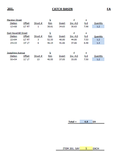
Source: MassDOT
Figure 18-5: Sample Earthworks Quantity Sheet
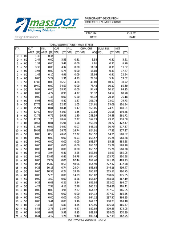
Source: MassDOT
Figure 18-6: Sample Earthworks Summary Quantity Sheet
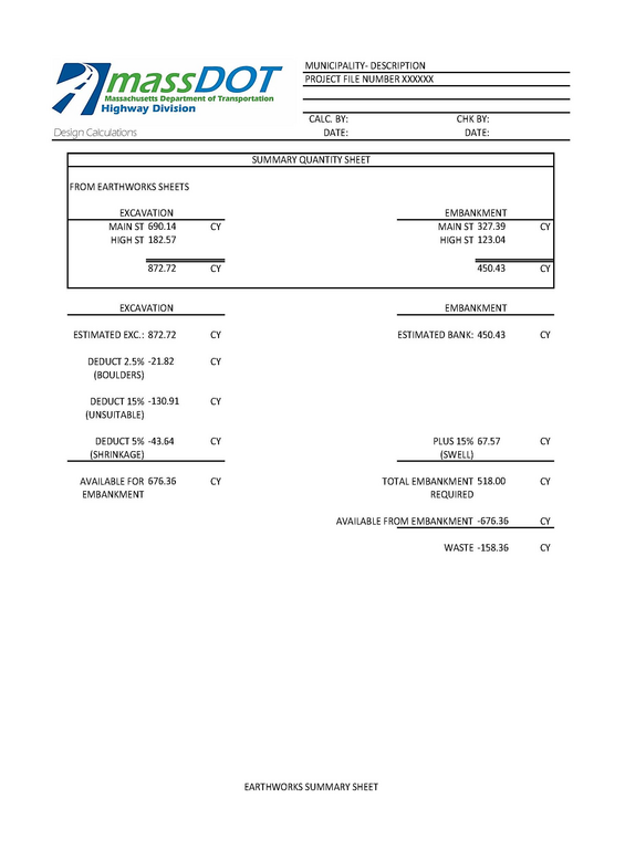
Source: MassDOT