8.1 Introduction
One of the most important considerations in roadway design is ensuring proper drainage of surface runoff from the roadway. Additionally, the design of roadways often affects the existing drainage patterns in the surrounding area. The designer also needs to ensure that adequate subsurface drainage is provided to maintain the integrity of the roadway structure.
Improper drainage poses significant safety hazards for all users of a roadway and can have a negative impact on the lifespan of the facility. Drainage design also needs to respect the integrity of natural watercourses, environmental resources, floodplains, and other features of the surrounding context. The evaluation of site hydrology and incorporation of stormwater management should be included early in the project development process and to the maximum extent feasible attempt to:
- Avoid and minimize impacts to wetland resource areas
- Reduce and minimize impervious surfaces
- Reproduce pre-development hydrologic conditions
- Fit the improvements to the terrain
- Use vegetated swales, basins, and/or medians
- Improve existing drainage systems
Another important component of drainage design is the preservation of water quality and the minimization of erosion. The flow of water over and adjacent to roadways can result in erosion of soils, which is detrimental both to the roadway’s structure and to the surrounding environment. The drainage design should minimize the potential for erosion.
Recognizing that roadway runoff is a potential source of water pollution due to the presence of contaminants (e.g., sediment, nutrients) transported by stormwater runoff, the designer should seek to prevent the discharge of untreated stormwater runoff to receiving waters. The designer must meet applicable regulations related to stormwater under the Wetlands Protection Act and 401 Water Quality Certification (i.e., the Massachusetts Department of Environmental Protection (MassDEP) Stormwater Management Standards), as applicable.
This chapter describes the Massachusetts Department of Transportation’s (MassDOT) procedures for drainage design, principles of hydrology applicable to drainage design, hydraulic design (design of drainage courses and structures), and erosion control during construction.
The MassDOT Stormwater Design Guide is the companion guidance to this chapter that focuses on stormwater control measures (SCMs) and treatment. The designer should use the latest version of this guidance document when designing stormwater management systems for roadways. The designer should also consult the various Federal Highway Administration (FHWA) Hydraulic Design Series (HDS) and Hydraulic Engineering Circulars (HEC) cited throughout the chapter as well as the American Association of State Highway and Transportation Officials (AASHTO) Highway Drainage Guidelines and the AASHTO Drainage Manual.
8.2 Procedures
The designer should complete the following tasks:
- Develop an understanding of the environmental context and constraints of the project.
- Become familiar with the environmental documents prepared for the project and incorporate appropriate mitigation measures into the project design.
- Investigate and address environmental concerns associated with adjacent wetlands such as stormwater discharge quality and quantity, flood storage capacity, groundwater quality and supplies, pollution prevention in sensitive resources areas, sedimentation, and erosion control.
- Determine whether there are any existing drainage problems that need be addressed as part of the project drainage design.
- Coordinate the drainage design with the roadway design to make sure that all low points adequately drain and that adequate cover is provided over all new drain lines.
- Refer to Chapter 13 to determine whether proposed medians, off road graded areas and drainage ditches can be vegetated to reduce the quantity of runoff.
- Design drainage improvements so that they can be easily maintained.
Drainage Law and the Designer’s Responsibility
Legal issues related to highway drainage can result from changes to natural drainage patterns caused by highway construction. To avoid these problems, the designer should minimize the adverse effects on adjacent property by using accepted drainage design methods. The designer should be particularly aware of the following legal requirements related to drainage design:
- Wetlands Protection Act (MGL Chapter 131, Section 40) — This act sets forth the requirements, procedures, and definitions to determine the effect of altering natural drainage patterns or wetland resource areas. It sets broad guidelines and limitations on the acceptable impacts of road and bridge construction.
- Wetlands Protection Act Regulations (310 CMR 10.00) — MassDEP regulates the discharge of stormwater to designated Resource Areas and/or associated Buffer Zones through the Wetlands Protection Act) with the Massachusetts Stormwater Management Standards. These Standards are currently implemented through regulatory authority at the local level (i.e., municipal conservation commissions) and may also be applied through various state regulations governing surface and groundwater quality (i.e., 401 Water Quality Certification). The Standards require the designer to develop a stormwater management system that prevents erosion, controls discharge rates, recharges groundwater, treats the quality of discharge (including higher treatment from certain land uses and for discharges to Critical Areas), provides erosion and sediment control during construction, provides operation and maintenance of the system, and conveys no illicit discharges.
- Section 401 Water Quality Certificate (314 CMR 9.00) — When a project involves activities proposing discharges to water bodies or wetlands, the designer should coordinate with the MassDOT Environmental Section and MassDEP regarding the permitting requirements under this section. These projects require State Water Quality Certification where MassDEP certifies that they will not violate the State Water Quality Standards. Other related requirements may apply such as those for water bodies on the MassDEP 303(d) List (i.e., category 5 on the Integrated List of Waters), the MA Surface and Groundwater Quality Standards and Permitting Programs or the MA Watershed Protection Act.
U.S. Environmental Protection Agency (EPA) National Pollutant Discharge Elimination System (NPDES) — In 1990, the U.S. EPA promulgated rules establishing Phase 1 of the NPDES stormwater program to address discharges from large Municipal Separate Storm Sewer Systems (MS4s), and in 1999, the EPA extended coverage of the NPDES stormwater program to small MS4s through the Phase II rule. The NPDES Phase II rule applies to MassDOT as an “operator of MS4s.” MassDOT obtained coverage under the 2003 NPDES General Permit for Stormwater Discharges from Small MS4s in Massachusetts (NPDES MS4 Permit) from EPA and MassDOT prepared a Stormwater Management Plan that describes MassDOT’s stormwater program and how it complies with the permit provisions. Phase II requires implementation of six minimum control measures including the following:
- Public education and outreach
- Public participation/involvement
- Illicit discharge detection and elimination
- Construction site runoff control
- Post-construction runoff control
- Pollution prevention/good housekeeping
The NPDES program also includes the Construction General Permit to address stormwater discharges from construction activities that involve land disturbance of one acre or more. Coverage under this permit requires filing of a Notice of Intent (NOI) with the EPA Region 1 office and preparation of a Storm Water Pollution Prevention Plan (SWPPP).
- The MassDOT Stormwater Design Guide - This guidance document developed by MassDOT provides the controlling guidance for MassDOT projects relative to compliance with the NPDES MS4 Permit and MassDEP regulations pertaining to stormwater management. The guide provides detailed guidance for the designer in preparing cost-effective stormwater management designs for roadway and bridge projects that comply with state and federal regulations. All MassDOT projects with stormwater components, including MassDOT-executed municipal projects, should follow the guidance in the MassDOT Stormwater Design Guide.
- The Massachusetts Public Waterfront Act (MGL Chapter 91, Waterways) — This act establishes the authority and limitations of MassDEP for any work affecting Boston Harbor, great ponds, shores along public beaches, tidelands, and coastal and inland waterways.
- MGL Chapter 83, Section 4 Drainage Easements and Liabilities — This act identifies the requirements for obtaining easements for construction or modification of drainage structures. Limits of liability are also established. When utilizing existing drainage outfalls, the designer should determine whether there is an existing drainage easement. If there is no existing drainage easement at the existing drainage outfall that is being utilized, or when designing new drainage outfalls, the designer should coordinate with the MassDOT Right of Way Section to obtain any required drainage easements.
- Section 404 Army Corps of Engineers (ACOE) — Federal law (33 USCA 404) requires that all construction activity involving navigable waters be reviewed and approved. Requirements include the 404 Application Form together with plans, drawings, and calculations for the construction activity (See 33 CFR 209). The designer should refer to Chapter 14 – Wildlife Accommodation for more information on the general permit.
- Massachusetts Environmental Policy Act (MEPA) — The designer should consult with the MassDOT Environmental Section regarding permitting requirements under 301 CMR 11.00.
- Federal Emergency Management Agency (FEMA) administers the National Flood Insurance Program (NFIP). FEMA has established regulations for modifications to floodways and floodplains. MassDOT coordination with FEMA is required under the following circumstances:
- A proposed crossing encroachment on a regulatory floodway that would require an amendment to the floodway map.
- A proposed crossing encroachment on a floodplain where a detailed study has been performed but no floodway designated and the maximum allowable (usually 1 foot) increase in the base flood elevation would be exceeded.
- A proposed crossing encroachment where a local community is expected to enter into the regular program within a reasonable period, and detailed floodplain studies are underway.
Details of requirements for meeting the conditions of FEMA and NFIP are contained in the following resources:
- FHWA paper Procedures for Coordinating Highway Encroachments on Floodplains with FEMA
- National Flood Insurance Program, Flood Insurance Manual, FEMA, April 2024
- National Flood Insurance Program Community Rating System, Coordinator’s Manual, FEMA (resource currently unavailable on FEMA website)
- National Flood Insurance Program Community Rating System, Addendum to the 2017 Coordinator’s Manual, FEMA (resource currently unavailable on FEMA website)
Figure 8-1 provides a schematic illustrating how FEMA determines a floodway, by encroaching on the floodway fringe to hit the maximum surcharge of 1.0 feet. If a Regulatory Floodway is present, note that there can be no surcharge or increase of the 100-year flood profile, upstream and downstream, as a result of a project. The designer should refer to 44 CFR 60.3 for floodplain management criteria for work in flood-prone areas. 44 CFR 60.3 is the basis of the local community’s floodplain management ordinance and provides the minimum requirements associated with regulations.
Figure 8‑1: Floodway Schematic
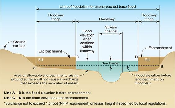
Source: FEMA Emergency Management Institute Course IS-0280, Figure 2-3
Other documents which provide additional guidance on legal matters are:
- Federal Floodplain Executive Order No. 11988,
- Federal Flood Risk Management Executive Order No. 13690,
- Federal Wetlands Executive Order No. 11990
- Federal Highway Program Manual, Volume 6, Chapter 7, Section 3, Subsection 2, "Location and Hydraulic Design of Encroachments on Flood Plains."
- Massachusetts Executive Order No. 149 “Provisions for State Coordination and Participation with the Federal Administration under the National Flood Insurance Act of 1968, as amended.”
- FEMA Guidance for Flood Risk Analysis and Mapping “Floodway Analysis Mapping.”
The designer should also consult the Massachusetts Wetlands Protection Act when considering any changes within the 100-year floodplain. The designated 100-year floodplain is included in the definition of Bordering Land Subject to Flooding or Land Subject to Coastal Flooding under the Wetlands Protection Act, regulated by MassDEP.
Coordination With Other Agencies
Modification of an existing drainage system can affect areas far removed from the construction area. The designer should be aware of future land use plans and any expected change to watercourses. The designer should investigate any planned future Federal, State and local agency actions affecting drainage in the watershed, including accepted Drainage Master Plans and local Department of Public Works, Conservation Commission and Watershed Council improvement efforts. Early environmental coordination with the environmental permitting agencies including MassDEP, ACOE and the local conservation commission(s) is recommended.
Documentation Necessary for Drainage Designs
The need for the drainage design should be established before undertaking any detailed investigation (e.g., Is there a flooding problem? Is the present culvert adequate? Is there visual or historic evidence of plugging with debris or sediment? Is there an existing erosion issue? Is the existing storm drain system adequate?).
New or Replacement Culvert — Once the decision to design a new or replacement culvert is made, the following information and coordination is needed:
- Plan, profile and bathymetry of the channel for distances of at least 500 feet upstream and downstream from the structure, or as directed. Review MassDOT Bridge Manual – Part I, Section 1.1.5 “Survey for Streams” for additional guidance
- Flagged wetland resource area boundaries under federal and state jurisdiction within 100 feet of culvert inlet and outlet locations
- Overbank (flood bank) sections, if required
- Dimensions of waterway openings and descriptive information of existing hydraulic structures, both upstream and downstream from the proposed structure
- Highwater elevations (upstream and downstream from existing highways) and date of occurrence
- Estimated flow velocity and depth during time of survey
- Roadway profile data to determine possible overtopping
- As-built or record plan and drainage reports for the existing culvert
- As-built or record utility plans in the vicinity of the existing culvert
- Stream geomorphic data
- Coordination with the MassDOT Environmental Section and the Massachusetts Division of Fisheries and Wildlife’s ’s Natural Heritage Program regarding documentation of threatened or endangered species
- Coordination with the MassDOT Environmental Section and local historic commission to determine whether the existing culvert has any historical significance
New or Replacement Storm Drain System —Once the decision to design a new or replacement storm drain system is made, the following information is required:
- Roadway plan, profile and cross-section (at 50-foot intervals) of the roadway within the project limits
- Existing storm drain system layout, and elevations including: drainage structure rim and invert elevations, condition, pipe materials, sizes and flow directions
- Location, condition and invert elevations of existing drainage outfalls including headwalls and flared-end sections
- Flagged wetland resource area boundaries under federal and state jurisdiction within 100 feet of existing drainage outfalls
- Highwater elevations observed at drainage outfalls and date of occurrence
- As-built or record plan and drainage reports for existing storm drain system
- As-built or record utility plans in the vicinity of the existing storm drain system
- Coordination with the MassDOT Environmental Section regarding documentation of threatened or endangered species, watershed Total Maximum Daily Load (TMDL), stressed basins, watersheds contributing to 303(d) listed water bodies or Outstanding Resource Waters as defined under MA Surface Water Quality regulation
- Compiled information regarding the location of private and public wells (and associated protective zones)
After receiving this information, the designer should conduct a preliminary analysis to determine the drainage requirements. The upstream and downstream limits of the drainage study should be based on the tributary watershed and the limits of any anticipated impacts of the proposed drainage improvements. This includes outlining the drainage areas on a topographic map and calculating the peak discharge. A field visit should be performed to verify and supplement the survey data and field truth the watershed delineations. The designer’s field investigation should provide the following information:
- Highwater elevations and evidence of scour
- Flooding problems and history obtained through personal interviews with local residents, state and municipal highway department personnel, and record information
- Evidence of erosion or presence of energy dissipation devices at existing drainage outfalls during time of survey
- Verification of watershed limits
- Estimated flow in channels
The designer must prepare and retain adequate documentation as part of the drainage design process. At a minimum, this includes:
- A statement of the objective(s) of the proposed drainage facility
- Conditions before and after construction (particularly any existing damage), including preconstruction photos along any natural watercourses (aerial photographs may be taken to supplement the ground photos)
- Drainage calculations with supporting data and assumptions made for these calculations
- A drainage area topographic map for the project site
All documentation should be consolidated into a package for the permanent project file. It should contain the name of the designer and reviewer and the completion date.
8.3 Hydrology
This section covers the hydrologic design process which includes:
- Selection of the design flood frequency
- Selection of the appropriate hydrologic method
- Determination of the peak design discharge
- Determination of the flood hydrograph and runoff volume, if required
Hydrology is the study of the properties, phenomena, and distribution of water. It is important to understand how an existing waterway behaves by conducting a hydrologic analysis before diving into design.
The hydrologic analysis will determine peak discharge rates for selected design storm return period(s). These rates are then used to determine the required sizes of the drainage facilities. The designer may also need to develop flood hydrographs and determine runoff volumes where flood storage capacity is a consideration and there is a need to maintain existing discharge volumes and peak rates.
Design Storm Frequency
The designer must select a design frequency to calculate the peak rate of runoff. Typical values are 2-, 5-, 10-, 25-, 50-, and 100-year storm frequencies. As an example, a 10-year storm means there is a 1/10 (0.10) probability that the peak discharge from that storm will be equaled or exceeded once during a given year.
Table 8-1 provides recommended design frequencies for closed drainage design. The designer should coordinate with MassDOT to determine if climate change projections or increased rainfall intensities or depth should be considered during the design.
Table 8-1: Recommended Design Flood Frequency For Storm Drain Systems
| Roadway Functional Class | Urban/Rural | Type of Installation: Storm Drain System2 Annual Chance (%) (Return Frequency (Years)) | Type of Installation: Open Channels3 Annual Chance (%) (Return Frequency (Years)) |
|---|---|---|---|
| Interstate/Freeway/Expressway | Both | 10% (10)4 | 2% (50) |
| Arterial | Urban Rural | 10% (10)4 10% (10)4 | 2% (50) 2% (50) |
| Collectors/Local | Urban Rural | 20% (5) 50% (2) or 20% (5) | 4% (25)5 10% (10) or 4% (25) |
Notes:
- The values in the table are typical ranges. The selected value for a project is based on an assessment of the likely damage of a given flow and the costs of the drainage facility.
- This includes pavement drainage design.
- This includes any culverts which pass under intersection roads, driveways, or median crossings.
- Use a 50-yr frequency at underpasses or depressed sections where ponded water can only be removed through the storm drain system.
- The selected frequency depends on the anticipated watershed developed and potential property damage.
Source: MassDOT
MassDEP Stormwater Management Standard #2 requires analysis of the 2-year, 10 year, and 100-year 24-hour storms to size peak discharge controls, if required. The emergency spillway for detention facilities should be designed for the 100-year storm. The MassDOT Stormwater Design Guide and the MassDEP Stormwater Management Standards should be consulted when determining whether peak discharge controls are required for a project.
Table 8‑2 provides recommended design frequencies for culvert/bridge crossings at roadways. The selected value for a project is based on an assessment of the likely damage from a given peak discharge and the initial construction and maintenance costs of the drainage facility. The designer should consider traffic interruptions, property damage, and possible loss of life. If the discharge from a greater design frequency can be accommodated, at a small additional cost, it should be considered.
Table 8‑2: Hydraulic Design, Scour Design and Scour Check Flood Selection Guidelines
| Highway Functional Classification | Hydraulic Design Flood AEP (%) (Years) | Scour Design Flood AEP (%) (Years) | Scour Check Flood AEP (%) (Years) |
|---|---|---|---|
| Interstate, or Limited Access Highways | 1% (100) | 0.5% (200) | 0.2% (500) |
| Rural Principal Arterial | 2% (50) | 1% (100) | 0.5% (200) |
| Rural Minor Arterial | 2% (50) | 1% (100) | 0.5% (200) |
| Rural Collector, Major | 4% (25) | 2% (50) | 1% (100) |
| Rural Collector, Minor | 10% (10) | 4% (25) | 2% (50) |
| Rural Local Road | 10% (10) | 4% (25) | 2% (50) |
| Urban Principal Arterial | 2% (50) | 1% (100) | 0.5% (200) |
| Urban Minor Arterial Street | 4% (25) | 2% (50) | 1% (100) |
| Urban Collector Street | 10% (10) | 4% (25) | 2% (50) |
| Urban Local Street | 10% (10) | 4% (25) | 2% (50) |
| Bike Trail/Shared Use Path | 10% (10) | 4% (25) | 2% (50) |
Note: Despite the fact that FHWA regulations require the use of at least a 50-year return frequency flood as the hydraulic design flood event for interstate highways, MassDOT requirement is the use of 100-yr return frequency. The designer should use professional engineering judgement based on environmental context and project goals when determining design flood frequency for their project.
Source: MassDOT Highway Division Bridge Manual – Part 1, Chapter 2, Table 2.6.3-1
Methods of Estimating Peak Discharge
Drainage design requires knowledge of the hydrologic characteristics of the area. MassDOT primarily uses three hydrologic methods to calculate peak runoff flow rates and/or volumes. This chapter offers a succinct summary of these methods. For a comprehensive understanding of the background and theory of these methods, designers are advised to consult the guidance documents referenced at the end of this chapter.
- U.S. Geological Survey (USGS) Regression Equations
- The Rational Method
- The Natural Resource Conservation Service (NRCS) Method
Each method will provide the estimated discharge in cubic feet per second (cfs) expected at a specific location for a given design frequency, drainage area, and set of hydrologic conditions. The designer should consider the hydrologic factors incorporated into the methods. Each method has its limitations. Refer to Table 8‑3 and Table 8‑4 for typical applications and limitations of each method.
In addition to the methods described below, the designer should also research existing USGS gauging station data and FEMA Flood Insurance Studies on existing rivers and streams for information regarding existing peak discharges.
At least two methods should be considered for each calculation, except roadway drainage, where only the Rational Method is necessary unless the design of peak discharge controls is required. If there is a wide range in peak discharge estimates between methods, the selection will be based on the experience of the designer and the most applicable method. The NRCS Method should be used when sizing peak discharge controls for roadway drainage.
When using any hydrologic method, the designer should consider future land use based on anticipated changes in the existing land use and any known development plans. The designer should check with the local planning agencies for this information.
Table 8-3: Typical Applications of Acceptable Hydrologic Methods
| Application | Rational Method | Hydrologic Methods NRCS TR-55 Method* | USGS Equations |
|---|---|---|---|
| Post Construction | |||
| Channel Protection | X | X | |
| Overbank Flood Protection | X | X | |
| Extreme Flood Protection | X | X | |
| Storage Facilities | X | ||
| Outlet Control Structures | X | X | X |
| Gutter Spread | X | ||
| Storm Drain Pipes | X | ||
| Culverts | X | X | X |
| Bridges | X | X | |
| Small Channels | X | X | X |
| Natural Channels | X | X | |
| Energy Dissipation | X | X | X |
*NRCS TR-55 method shall be calibrated to USGS regression equations when used
Source: MassDOT
Table 8-4: Limitations for Hydrologic Methods
| Method | Watershed Area Limitation |
|---|---|
| Rational | 0 - 200 acres |
| NRCS TR-55 Method | Usually < 2,000 acres and has hydrologic homogeneity |
| USGS Urban Regression Equations* | See most current USGS publication |
| USGS Rural regression Equations* | See most current USGS publication |
*USGS regression equation should not be used to calculate peak flow in basins less than 200 acres.
Source: MassDOT
USGS Regional Regression Equations
Peak stream flow records have also been used together with known basin characteristics to produce regionalized peak flow rate equations applicable to all streams within similar physiographic regions. The USGS developed regional regression equations by performing a regression analysis on drainage basin characteristics to determine which were most highly correlated to peak flow rates. The regional regression equations relate peak flow rate for a specific recurrence interval to a particular basin’s characteristics. Separate equations are used for large and small basins that are primarily rural and for those that are primarily urban.
Regional regression equations are used to estimate the peak flow rates. USGS reports describe these regression equations, which vary in applicability by region and can be used for various drainage area ranges.
Regional USGS regression equations are documented in greater detail in USGS Scientific Investigation Report 2016-5156 “Magnitude and Flood Flows at Selected Annual Exceedance Probabilities for Streams in Massachusetts.”
If applicable, designers may be able to obtain this information using USGS StreamStats Application.
The Rational Method
The Rational Method is a procedure for estimating peak flows from small drainage areas with large amounts of impervious area based on runoff coefficients, rainfall intensity, and drainage area. This method is a simplified model of the hydrologic process and should only be used for small drainage areas, and preferably for areas with the same general basin characteristics. It should be the primary method used to determine the peak discharge for pavement drainage and storm drain system design. Because of inherent assumptions, the Rational Formula should only be applied to drainage areas smaller than 50 acres.
Rainfall intensities should be determined using the National Oceanic Atmospheric Association Atlas (NOAA) 14-Precipitation-Frequency Atlas of the U.S. Volume 10, Version 3.0: Northeastern States (NOAA Atlas 14).
The Rational Method is described in greater detail in Urban Drainage Design Manual, HEC #22, FHWA (Section 4.2.2). See Example 4.3 in HEC #22 for a demonstration of an estimation of peak flow using the Rational Method.
The NRCS Method
The NRCS method (formerly the SCS method) estimates runoff from storm rainfall and uses the runoff curve number (CN) method. Determination of CN depends on the watershed’s soil and cover conditions, which the model represents as Hydrologic Soil Group (HSG), cover type, treatment, and hydrologic condition. A series of charts are used to determine the peak flows based on runoff CN, watershed slope (flat, moderate, or steep), and 24-hr precipitation depth for the design frequency.
Twenty-four-hour rainfall depths and site-specific rainfall distributions should be determined using NOAA Atlas 14. NRCS rainfall distributions based on NOAA Atlas 14 precipitation depth data, or “nested” synthetic storm distributions, should be created by embedding shorter duration precipitation depths into a 24-hr distribution to create a site-specific distribution. These new site-specific distributions replace the obsolete NRCS/SCS Type I, IA, II, and III distributions. NRCS has developed Atlas 14 Volume 10 rainfall distributions for Northeastern states, published in WinTR-55 v2 as N10_A, N10_B, etc. Some modeling programs include these distributions as options. For further information, consult Chapter 4 of the NRCS Part 630 Hydrology National Engineering Handbook, which provides guidance on developing rainfall distributions using Atlas 14 data.
The NRCS Method is described in greater detail in Technical Release No. 55 (TR-55), Urban Hydrology for Small Watersheds, U.S. Soil Conservation Service.
The NRCS Method can also be used to develop flood hydrographs and calculate runoff volumes necessary for designing peak discharge controls. The designer should consult TR-55 when developing flood hydrographs, calculating runoff volumes and designing peak discharge controls. The TR-55 and TR-20 computer programs are available from the Tech Tools Resources section of the National Resources Conservation Service. Computer software utilizing the NRCS Method is also available from various other computer software companies.
Effects of Storage
Storage has the effect of reducing the peak discharge, thus reducing the required sizes of the drainage structures. Each of the hydrologic methods used, except the Rational Method, can account for natural storage (swamps and ponds) that is spread throughout the drainage area. The NRCS Method has adjustment factors for natural storage near the design site. Natural (or man-made) storage at the upper reaches of the watershed area is usually ignored, depending on the level of the detail required by the hydrologic evaluation. The designer must consider any future changes in the existing upstream watershed that could reduce existing storage capacity in the future.
The effects of man-made storage areas, such as reservoirs and flood control systems, should also be evaluated. The designer should refer to the procedures in Chapter 10 of HEC #22 for estimating the effects of detention on watershed hydrology.
The NRCS Method can be used to develop flood hydrographs and estimate runoff volumes that can be used in evaluating the storage capacity of existing drainage systems, particularly at the inlet side of existing culverts.
The NRCS Method can also be used to size proposed stormwater basins (e.g., infiltration basins, stormwater wetlands, bioretention areas, extended dry detention basins, wet basins) that can provide additional storage to mitigate increases in peak discharge. The designer should use the MassDOT Stormwater Design Guide to determine whether stormwater basins will need to be designed to mitigate increases in peak discharge as part of the project.
Detention storage facilities are designed to reduce peak discharge and detain runoff for short periods of time. The following information, at a minimum, is required to prepare a detention storage facility design:
- Inflow hydrograph for all selected design storms
- A stage-storage curve defining the relationship between the depth of water and the storage volume of the proposed facility
- A stage-discharge curve defining the relationship between the depth of water and the discharge or outflow for all outlet control structures to be used on the proposed facility
A general procedure for performing a detention storage facility design is presented in Example 10.1 in HEC #22.
8.4 Hydraulic Design
This section discusses the design of closed drainage systems, open channel conveyances, stormwater culverts, energy dissipation measures, and subdrainage. It also covers design considerations for stream or riverine systems and any conveyance structures for those systems. Refer to the MassDOT Highway Division Bridge Manual for design guidance on bridges. Please note that any change to streams and rivers as a result of a MassDOT project, permanently or temporarily, should be brought to the attention of MassDOT’s hydraulic unit via a formal memorandum.
Definitions
There are many important definitions to understand in hydraulic, hydrologic and drainage design:
Allowable Headwater (AHW) — the maximum allowable ponding elevation at the culvert entrance, as measured from the culvert invert.
Critical Depth — the depth of flow at which the discharge is maximum for a given specific energy, or the depth at which a given discharge occurs with minimum specific energy.
Critical Flow — exists when the discharge is maximum for a given specific energy head or, conversely, when the specific energy head is minimum for a given discharge.
Critical Slope — the slope which will sustain a given discharge at uniform critical depth in a channel.
Critical Velocity — the mean velocity when the discharge is critical flow.
Energy Grade Line (EGL) — the line representing a conceptual link of the energy states between two channel or conduit locations. The energy state is defined by the sum of pressure, velocity, and elevation heads. The slope of the EGL is frequently referred to as the friction slope. The EGL equals the HGL plus the velocity head.
Energy Gradient — the slope of the EGL, usually parallel to the hydraulic gradient.
Freeboard — the distance between the AHW and some Source point (e.g., the edge of the pavement surface).
Headwater (HW) — the vertical distance between the invert at the culvert inlet and hydraulic grade line (water surface). For a given set of conditions (discharge, culvert size, etc.), a certain HW depth will develop to provide the required head to force the discharge through the culvert.
Hydraulic Grade Line (HGL)— the line representing the level of flowing water in an open channel. In closed pipes, the HGL represents the level to which water would rise in a vertical tube at any point along the pipe. It is equal to the EGL elevation minus the velocity head.
Hydraulic Gradient — the slope of the HGL.
Inlet Control — discharge capacity which is controlled by the conditions at the culvert entrance, including the depth of headwater and entrance geometry (barrel shape, cross-sectional area, and type of inlet edge). See Figure 8‑4.
Non-Uniform Flow — occurs when the depth of flow changes along the length of the open channel.
Outlet Control — discharge capacity which, in addition to the entrance conditions, is controlled by the culvert characteristics and outlet conditions, including culvert length and slope and depth of tailwater. Culverts in outlet control may flow full or part full for all or part of the culvert length. See Figure 8‑5.
Specific Energy — the total energy head at a cross section measured from the bottom of the channel. It is the sum of the potential head (depth) and the velocity head (kinetic energy).
Steady Flow — exists when the quantity of water passing any section is constant with time. At any point, the rates of inflow and outflow must be constant and equal.
Subcritical Flow — flow which occurs when the depth is greater than critical depth and the velocity is less than critical velocity.
Supercritical Flow — flow which occurs when the depth is less than critical depth and the velocity is greater than critical velocity.
Tailwater (TW) — the vertical distance between the invert at the culvert outlet and HGL (depth of water). TW will often be determined by conditions downstream from the culvert.
Uniform Flow — results from a constant channel cross section, grade, and roughness. The depth, slope, and velocity will remain constant over a given length of channel. The slopes of the channel bottom, hydraulic gradient, and energy gradient are equal.
Unsteady Flow — exists when there are variations in the discharge with time.
Velocity Head — the kinetic energy of the flow which equals the difference between the HGL and EGL, and is expressed by:
HV = V2/2g
where:
V = velocity, (ft/sec)
g = gravitational acceleration, 32.2 ft/s2 (9.81 m/s2)
Roadside Drainage (Open Channels)
Roadside drainage channels remove and divert surface runoff from the highway right-of-way. Normally, they are the least expensive means to provide highway drainage.
Roadside drainage channels and median swales can also be used to lengthen the time of concentration by creating longer flow paths and using rough and vegetated channel linings. Drainage channels and median swales can also be converted into linear stormwater control measures with permanent check dams to promote infiltration, detention, and treatment through the use of vegetation, ponding behind check dams, and natural substrates. See the MassDOT Stormwater Design Guide for guidance on designing stormwater linear practices with permanent check dams.
Figure 8‑2 illustrates several types of roadside drainage controls. These are:
- Roadway Channels— provided in cut sections to remove the storm runoff.
- Toe-of-Slope Channels — provided at the bottom of a slope to convey the storm runoff from roadway channels to a discharge point.
- Intercepting Channels — provided longitudinally at the top of a cut to intercept runoff from the hillside before it reaches the roadway.
- Paved Waterways (not shown in figure) — usually steeply inclined open channels having an armored invert which convey water to a lower level.
- Median Swales — shallow, depressed areas in medians which drain the median area of a divided highway.
- Gutters (not shown in figure) — channels at the pavement or shoulder edges which drain the roadway surface.
Figure 8‑2: Types of Roadside Drainage Controls
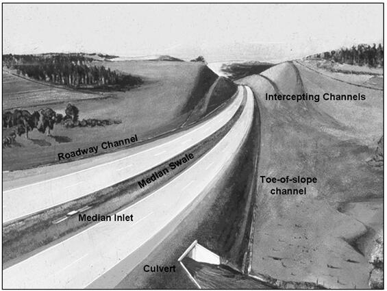
Source: FHWA HDS #4, Figure 1.1
References for roadside drainage design include:
- Introduction to Highway Hydraulics, HDS #4, FHWA
- Design of Roadside Channels with Flexible Linings, HEC #15, FHWA
- Urban Drainage Design Manual, HEC #22, FHWA
Refer to the FHWA for the latest guidance.
Channel Capacity
The open channel must be designed to accommodate the peak discharge for the design frequency. The Manning equation is used to calculate the flow velocity. Refer to Section 6.1.4 of HEC #22 for guidance on using the Manning equation for open channel flow.
The Manning equation is used for open channel flow and unsubmerged culverts. The design of the pressure flow through culverts is discussed in Section 9.1.2 of HEC #22. For most roadside drainage design, the designer can assume steady, uniform flow, which is discussed in Section 6.1.3 of HEC #22.
Channel Cross Section
Following are the standard MassDOT cross sections for roadside drainage:
- Trapezoidal — This is the standard ditch section for a roadside channel. See the MassDOT Construction Standards.
- Semi-Circular — An Asphalt-Coated Corrugated Metal pipe is typically used for intercepting channels at the top of slopes. See the MassDOT Construction Standards.
- Parabolic — A 4-inch-deep parabolic ditch section (paved waterway), using bituminous or cement concrete, is also used. See the MassDOT Construction Standards.
Channel Gradient
The desired minimum grade is 0.005 ft/ft for paved channels. For grass channels, the desired minimum grade is 0.01 ft/ft. To avoid sedimentation, the gradient should remain constant or increase in the downstream direction.
Channel Alignment
The designer should avoid abrupt changes in alignment. If possible, alignment changes should be made where flow is subcritical. Refer to HDS #4 Chapter 4 for a detailed discussion of the hydraulic analysis associated with changes in alignment.
Channel Linings
Channel linings protect the channel section from erosion and reduce maintenance. Channel linings should also be selected to maximize stormwater treatment through filtration and infiltration. The use of grass, cobbles, or stone over impervious surfaces such as concrete or asphalt is encouraged.
MassDOT's criteria for roadside ditch linings are:
- Grades up to 2% — grass or sod*
- Grades 2-3% — jute mesh with loam and seed or other suitable material
Grades over 3% — either rock lined, paved or approved lining
*applies to grass channels with rye-dominant grass and flow depths less than 12 inches
The designer should use professional engineering judgement to select an appropriate channel lining on grades over 3% and in areas with elevated risk for channel erosion. In addition to channel slope, the designer should consider velocity, changes in direction, shear stress, aesthetics, natural environment, and drainage criteria. Refer to HEC #15 and Section 6.3 of HEC #22 for further guidance on channel lining selection and design.
Culverts
A culvert is a structure which provides an opening under the roadway. (Culverts are not federally classified as a bridge if their span is less than 20 feet; however, in Massachusetts, structures with spans between 10 to 20 feet may be classified as short span bridges). Culvert cross sections include rectangular (box), circular, arch, and oval. Materials include concrete, corrugated plastic pipe, steel and aluminum. Some existing culverts may be constructed of stone masonry. Culvert design and construction is standard for small sizes which are prefabricated by manufacturers. Structural-plate pipe arches and precast concrete box culverts may be used for larger culverts. TheMassDOT Construction Standards provide the design details for box and pipe culverts.
The basic references for the design of culverts are:
- Hydraulic Design of Highway Culverts, HDS #5, FHWA
- Hydraulic Design of Safe Bridges, HDS #7, FHWA
- Hydraulic Design of Energy Dissipators for Culverts and Channels, HEC #14, FHWA
- Culvert Design for Aquatic Organism Passage, HEC #26, FHWA
- Fish Passage in Large Culverts with Low Flows, FHWA, 2014
- Effects of Inlet Geometry on Hydraulic Performance of Box Culverts, FHWA, 2006
In addition, several computer programs are available for the hydraulic design of culverts, including:
- HY-8 — Culvert Analysis
- FHWA Engineering Toolbox
- Hydrologic Engineering Center’s River Analysis System (HEC-RAS)
Design Responsibility
The designer will be responsible to design most culverts; however, the designer may refer large culverts which present unusual problems to the Hydraulic Section. General terms used in culvert design are shown in Figures 8-3 through 8-5 below and definitions are provided at the beginning of this section.
Figure 8-3 shows a culvert with the visual definitions of headwater, tailwater, hydraulic grade line, energy grade line, and several head losses. The energy grade line is above the hydraulic grade line with the vertical distance between them equal to the velocity head.
Figure 8‑3: Culvert Definition Sketch
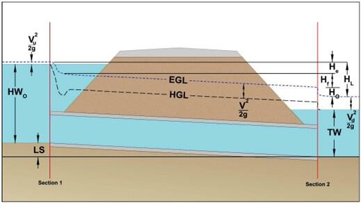
Source: FHWA HDS #5, Figure 3.8
Figure 8-4 shows culverts under various inlet control conditions with varying combinations of submersion and flow type.
Figure 8‑4: Inlet Control
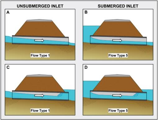
Source: FHWA HDS #5, FIGURE 3.1
Figure 8-5 shows culverts under various outlet control conditions, with varying combinations of submersion and flow type.
Figure 8‑5: Outlet Control
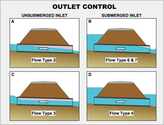
Source: FHWA HDS #5, Figure 3.7
Basic Design Criteria
The basic design criteria for culvert design are described in the following paragraphs.
- Allowable Headwater (AHW) — The minimum desirable freeboard is 2 feet between the AHW and the roadway overtopping elevation. The allowable headwater will be limited by one or more of the following:
- Non-damaging to upstream property
- Below the traffic lanes of interest or no higher than the shoulder or 1.6 feet below the edge of shoulder
- Equal to a headwater depth to barrel height (HW/D) no greater than 1.5
- No greater than the low point in the road grade
- Equal to the elevation where flow diverts around the culvert
- In addition, the designer should also consider:
- Existing and future land use in the watershed
- Potential pavement damage when water rises above the subbase elevation
- FEMA 100-year flood requirements
- Bordering Land Subject to Flooding and Bordering Vegetated Wetlands requirements
- Debris
- The need to create lower-than-existing headwater ponding in flood-prone or sensitive areas upstream from the culvert
- Overbank flooding and resultant overtopping of the highway at a roadway low point away from the culvert location
- Minimum Size — 15-inch diameter for driveways and median culverts; 18-inch diameter for roadway cross culverts and 24-inch diameter for interstate roadways.
- Safety — Preferably, cross culvert end sections should be extended beyond the roadside recovery area as presented in Chapter 5. If within the recovery area, the end section should be designed to fit the embankment side slope. Otherwise, guardrail may be warranted. Roadside and median culverts within the recovery area should also be designed to fit the embankment slope, if practical. The desirable slope for these cases is 10:1; it should not be steeper than 6:1.
- Stream Stability — When new culvert crossings of rivers or major streams are planned, the designer should conduct an assessment of the existing stream and river conditions that affect the road alignment, culvert placement and design. The assessment should include a geomorphic analysis of the affected stream and a determination as to whether the stream is aggrading, degrading or stable. In preparing the geomorphic analysis the designer should consult Stream Stability at Highway Structures, HEC #20 , FHWA.
- Wildlife Accommodation — New stream crossings requiring authorization under the Wetlands Protection Act must meet the Massachusetts Stream Crossing Standards. Replacement crossings requiring a 401 Water Quality Certification or authorization under the Wetlands Protection Act or the ACOE General Permit for Massachusetts need to meet the Massachusetts Stream Crossing Standards to the maximum extent practicable. The designer should refer to Chapter 14 – Wildlife Accommodation for further guidance on stream simulation and embedment for culverts.
- Outlet Velocity — The outlet velocity should be checked to make sure that it will not result in erosion or scour of the downstream channel bottom. See Section ”Energy Dissipators” for more on design.
- Tailwater — When establishing a tailwater condition near a confluence, a joint probability analysis should be conducted in accordance with Stream Stability at Highway Structures, HEC #19, FHWA.
- Inlet Protection and Seepage — Culvert failure can occur due to inlet failures and seepage along the culvert barrel which can cause washout of supporting material. Good compaction of backfill material is essential to reducing culvert failure and anti-seep collars should be considered to prevent "piping" of water along structures.
Capacity Factors
The capacity of culverts operating with inlet control is determined by culvert size, inlet geometry, and headwater. The capacity of culverts operating with outlet control is determined by culvert size, inlet geometry, headwater (HW), tailwater (TW), and culvert slope, roughness and length.
Inlet treatment will affect the entrance losses at the headwater. The standard types of treatment include (in order of increasing efficiency): projecting pipes; cut to fit the embankment slope (either by mitering or with a standard end section); and headwalls (with a beveled edge or with wingwalls). Following is general MassDOT policy for culvert inlets:
- Box Culverts — A wingwall with headwall should normally be provided. The range of angles is 30 degrees to 75 degrees (typically 45 degrees) as measured from the longitudinal axis of the culvert.
- Concrete Pipes — A grooved end (bevel) should be provided. The decision to provide a headwall or to project the end is based on the highway cross-section.
- Corrugated Metal Pipes — The decision to provide a headwall, mitered or standard end section, or projected, will be based on the highway cross-section and safety (See NRCS Method under Section 8.3). Mitered or projected end sections may require stone protection to prevent erosion and scour.
Inlet geometric improvements can significantly increase the capacity of culverts operating with inlet control. They provide some improvement to those operating with outlet control. HDS #5 discusses these improvements in detail. Three types of inlet improvements can be considered: bevel-edged, side-tapered, and/or slope-tapered.
Energy Dissipators
Open channels and culverts may significantly increase the erosion of the natural channel bed at their outlet. This is particularly true of culverts. Erosion and scour will occur if the outlet conditions produce excessive flow velocities. In these cases, either altering the design of the culvert or providing an energy dissipator should be evaluated. Otherwise, the culvert may fail. The basic source for the design of energy dissipation is HEC #14.
If needed, the type of energy dissipator will depend on the following:
- discharge volume and velocity
- culvert size, slope, roughness, and outlet geometry
- natural channel material
- TW depth
- Froude number (F) range
When the design of an energy dissipator is required for new culvert crossings on rivers or streams that support one or more species of fish, or on a known amphibian or other wildlife crossing, the designer should refer to Chapter 14 - Wildlife Accommodation since these devices may impact the ability of wildlife to pass through the culvert.
The highest outlet velocities will be produced by long, smooth-barrel culverts on steep slopes. These culverts are the most likely candidates for energy dissipators. However, protection may also be necessary for culverts on mild slopes. TW is also a major factor. High TW will reduce the outlet velocity and, therefore, the erosion potential. In addition, the erodibility of the natural stream material at the outlet will influence the amount of scour.
The Froude number is:
F = [ V / √g dm ] = V / Vc
Where:
dm = Mean depth of flow (ft)
g = 32.2 ft/s2
V = mean velocity (ft/s)
Vc = critical velocity (ft/s)
The Froude number represents subcritical (F < 1), critical (F = 1), or supercritical (F > 1) flow. In the selection of energy dissipators, F will indicate which type is best for the hydraulic conditions (see Table 1.1 in HEC #14).
Applicability
The designer must estimate the potential erosion or scour at the culvert outlet to determine the need for culvert modifications or an energy dissipator. If an existing culvert is being re-evaluated, a field inspection of the outlet should be made to examine the existing erosion. The soils information, maintenance history, culvert characteristics, and discharge history (if available) should be reviewed.
The designer should estimate the potential scour of new and existing culverts by the procedures in Chapter 5 of HEC #14. The method provides an estimate of the depth, width and length of scour based on the TW depth, culvert dimensions and a time variable. The procedure is inexact and meant to serve as only an approximate means to estimate scour.
Culvert Modifications (New or Existing)
If the designer concludes that scour will occur, they should first consider altering the culvert characteristics to correct the problem. Possibilities include:
- Increase the culvert size to reduce outlet velocity. This may be effective on mild slopes but is generally ineffective on steep slopes.
- Increase the number of culvert barrels.
- Provide a wingwall in conjunction with a square-edged headwall. This is applicable for culverts in outlet control where subcritical flow is present throughout the structure. Under specific circumstances, it may also be applicable to supercritical flow.
- Consider corrugated metal pipe with a higher “n” value to reduce the flow velocity.
Types of Energy Dissipators
If the culvert cannot be modified, or if the design options of a proposed culvert are limited, an energy dissipator should be used at the outlet or within the culvert barrel.
- Internal Dissipators — Roughness elements may be added internally throughout the culvert or just prior to the outlet to slow the velocity in the culvert.
- Stilling Basins — Basins characterized by some combination of chute blocks, baffle blocks, and sills placed at the outlet of a culvert designed to trigger a hydraulic jump in combination with a required TW condition. With the required TW, a properly designed stilling basin has velocities leaving the basin equal to the velocities in the receiving channel.
- Streambed Level Dissipators — Dissipators for culvert outlets designed to operate at the streambed level to reestablish natural flow conditions downstream from the outlet and drain by gravity when not in operation.
- Drop Structures — A steep slope for culverts or open channels may be converted to a series of gentle slopes with intermittent vertical drops into a stilling basin. This arrangement will prevent the erosive high velocities from developing.
- Riprap Basins and Aprons — Large angular and rounded stones are used at the culvert outlet to dissipate the kinetic energy. A filter blanket should be used as a foundation for the stone. Riprap should be sized in accordance with Chapter 10 of HEC #14.
- Stilling Wells — These dissipate the kinetic energy by forcing the flow to travel upward to reach the downstream channel.
Design Procedure
The following procedure should be used to select and design an energy dissipator. HEC #14 describes the analytical details:
- Identify and collect design data (culvert data; transition data; channel data; allowable scour estimate; and stability assessment).
- Evaluate velocities. Compute the culvert exit velocity and compare with the downstream channel velocity.
- Evaluate the outlet scour hole. See Chapter 5 of HEC #14.
- Design alternative energy dissipators. Compare the design data to the attributes of various energy dissipators in Table 1.1 in HEC #14.
- Evaluate the practicality of modifying the existing culvert to eliminate the potential scour. See the section “Culvert Modifications (New or Existing).”
- Select an energy dissipator. Compare the design alternatives and select the dissipator that has the best combination of cost and velocity reduction.
Storm Drain Systems
A storm drain system is a closed system which conveys storm runoff. Inlets, manholes, collector pipes, the main trunk line, and outlet(s) form the system. It is often used in urban and suburban areas with curbed roadways, where roadside ditches are unacceptable. The basic reference for the design of a storm drain system is:
Pavement Drainage
Storm discharge from pavements will contribute a majority of the water that the storm drain system must handle. The amount of discharge for the selected design frequency will depend on the rainfall intensity and the pavement grade, width, and cross slope. The designer must select a tolerable spread (T) on the pavement to evaluate pavement drainage (see Figure 8‑6). The spread will depend on the pavement discharge and the capacity and spacing of the gutter inlets (see the section below on “Gutter Inlets”). These criteria apply to the road classifications and contexts shown in Table 8-5 below.
Table 8-5: Minimum Design Frequency and Spread
| Roadway Functional Classification | Context | Design Frequency Annual Chance (%) (Return Frequency (Years)) | Design Spread |
|---|---|---|---|
| Interstates, Freeways, Expressways, & Arterials | Design speeds ≥ 45 mph Design speeds < 45 mph Sag vertical curve/ depressed roadway | 10% (10) 10% (10) 2% (50) | Shoulder Shoulder + 3 ft Shoulder + 3 ft |
| Collectors | Design speeds ≥ 45 mph Design speeds < 45 mph Sag vertical curve/ depressed roadway | 10% (10) 10% (10) 10% (10) | Shoulder 1/2 Driving Lane 1/2 Driving Lane |
| Local Roads | High ADT Low ADT Sag Point | 20%-10% (5-10) 50%-20% (2-5) 10% (10) | 1/2 Driving Lane 1/2 Driving Lane 1/2 Driving Lane |
Source: MassDOT
Where the above guidance results in a tolerable spread of less than 6 feet, the tolerable spread shall be 6 feet.
The Rational Method (see the section “Methods of Estimating Peak Discharge”) is used to calculate the discharge from pavements. The minimum time of concentration (Tc) is assumed to be 5 minutes, which is then used as the rainfall duration for the first inlet structure.
Figure 8-6: Width of Spread

Inlet Structures
MassDOT uses the following types of inlets to collect storm runoff:
- Catch Basins
- Gutter Inlets
- Drop Inlets
- Paved Waterways/Curb Cuts
- Trench/Slotted Drains
These inlet types are described below. For inlets on certain projects, hoods may be appropriate since they trap floatables, oil, and grease. The designer should consult the MassDOT Stormwater Design Guide for locations where hoods are required.
- Catch Basins — A grate is used to intercept storm runoff which is delivered to an underground structure (usually an inside diameter of 4 feet) with a 4-foot sump to help remove suspended solids from the stormwater. Catch basins can be constructed using concrete block, or precast concrete. Two types of MassDOT standard grates are typically used: parallel bar grates and Massachusetts cascade grates.
- Gutter Inlet — A grate is used to intercept storm runoff which is delivered to an underground structure (2-feet square) without a sump. It is designed for locations where utilities make a full-size catch basin impossible. They can be either brick or concrete as described in the MassDOT Construction Standards. When a gutter inlet is used, a catch basin with a 4-foot sump and manhole frame and cover should be installed between the inlet and trunk line manhole. A curb inlet may also be used where curbing is required.
- Drop Inlet — A grate and side-opening “throat” are used with a 2- to 3-foot sump, and may warrant the use of hoods to capture trash that otherwise would have been screened-out by catch basin grates. These are typically used in ditches and in stormwater basins as the outlet control structure. A raised type is used where run-off-the-road vehicles cannot hit the drop inlet; a flush type is used where the inlet can be a hazard. MassDOT Construction Standards provide the design details.
- Paved Waterways/Curb Cuts — A paved waterway is a device used to convey channelized gutter flow off the pavement via a break in the curb/berm and a slightly depressed section redirecting the runoff. The paved waterway discharge is considered a point source discharge, so design and installation of proper erosion controls should be considered.
- Trench/Slotted Drain — Trench drains and slotted drains are long, linear structures where a top grate or slot sits flush with or slightly below the pavement and has an opening or pipe underneath to convey water. Trench drains and slotted drains are typically only used for temporary conditions during construction.
Grate Types
MassDOT has two standard grate types: parallel bar grates and cascade grates. These can be used on catch basins, gutter inlets, and drop inlet structures.
- Parallel bar grates — These grates have long narrow slots that are placed parallel to the flow. Each full slot is 1.2” wide and 21” long. These grates should only be used on limited access highways where bicycles are not allowed.
- Cascade grates — These grates have slanted rectangular openings placed so that flow follows the slant into the basin below. The openings are approximately 4.06” by 4.44”. These grates should be used on all non-limited access roadways and must be used where bicycles are allowed. Cascade grates should not be used at low points.
MassDOT allows the use of double-grated structures to address inlet capacity and/or spread issues. When located at low points, double grates should be configured so that the long edge runs along the curb line. In some locations, double grates may be placed so that the short edge runs along the curb line, but only when the entire inlet frame sits outside of the travel lane.
The MassDOT Construction Standards provide the design details for catch basins and grates. A curb inlet may also be used where curbing is required. The efficiency of these grates is shown in Table 8-6.
Designer Notes Regarding Use of Modeling Software: Use professional engineering judgement to either create custom inlet types and/or grates or to select the appropriate default inlet types and/or grates, considering bypass flow and splash over.
Table 8-6: Grate Inlet Efficiency (E)
| Allowable Width of Spread (T) | |||||||||
|---|---|---|---|---|---|---|---|---|---|
| Grate | 2' | 3' | 4' | 5' | 6' | 7' | 8' | 9' | 10' |
| Parallel Bar | .95 - 1.00 | .92 - .99 | .83 - .94 | .74 - .86 | .66 - .78 | .59 - .71 | .54 - .65 | .49 - .60 | .45 - .56 |
| Mass. Cascade | .91 - 1.00 | .87 - .99 | .79 - .93 | .70 - .85 | .63 - .77 | .56 - .70 | .51 - .64 | .46 - .59 | .43 - .55 |
Source: MassDOT
Inlet Placement
Inlets must be placed to capture water, prevent flooding, and promote safety. The following is general guidance for placement:
- Catch basins should be designed as “end of line” devices with each catch basin connected to a drain manhole rather than connected to another catch basin in series.
- Six inlets should be used at low points on major highways: one on each side of the roadway at the low point and one on each side of the low point at locations approximately 0.3 feet (elevation distance) above the low point.
- Four inlets should be used at low points on minor highways: one on each side at the low point and one on each side 20 to 25 feet (horizontal distance) from the low point on the lesser of the two upgrades.
- Inlets should be placed at the following specific locations:
- Upgradient of intersections and pedestrian crosswalks.
- On superelevated curves, before the superelevation transition begins.
- On the upgradient side of bridges.
- At low points in open channels.
- Along the edge of roadway so that the tolerable ponding on the travel lane is not exceeded. General guidelines for spacing are as follows:
- 300± feet on tangent, or closer as required for intersections.
- 200-250 feet on the inside of superelevated curves. The closer spacing should be used for wider pavements.
- 250 feet on highway grades over 6%.
Inlet capacity and spread should be checked to determine if closer catch basin spacings are warranted. The final decision on placement should be based on engineering judgment.
Gutter Spread
The designer should analyze the capacity of the gutter and grates to determine if additional catch basins are required. See Table 8-5 for allowable gutter spread.
In areas prone to leaf accumulation, designers should use professional engineering judgement to select an appropriate clogging factor. See Section 7.1.3 HEC #22 for further guidance on clogging factors.
Designer Notes Regarding Use of Modeling Software: Modeling software can account for the distribution of flow captured by inlets versus bypass flow. Where software or hand calculations are unable to account for this, grate efficiencies shown in Table 8-6 can be used to determine percentage of flow capture versus bypass. If using modeling software, ensure model is accounting for bypass; do not assume full (100%) capture.
Manholes
Manholes are underground structures and provide access for maintenance to the storm drain system. They are typically located at junctions, at intermediate points on long tangent pipe runs, where the conduit changes sizes, and at changes in grade or alignment.
The spacing of manholes should be in accordance with the criteria in Table 8‑7:
Table 8‑7: Criteria for Spacing Manholes by Size of Pipe
| Size of pipe | Maximum Distance |
|---|---|
| 12-24 inch | 300 feet |
| 30-36 inch | 400 feet |
| 42-54 inch | 500 feet |
| 60 inch and greater | 1,000 feet |
Source: MassDOT
Deflection angles in the trunk line produce head losses at the manhole, which will increase the HGL. Deflection angles up to 90 degrees are acceptable if the head losses are calculated for the HGL computation. As general guidance, pipe diameters up to 36 inches may have deflection angles up to 60 degrees at manholes. These angles are measured between the centerlines of the inflow and outflow trunk line.
Where inlet or lateral pipes connect to the trunk line at a manhole, the maximum deflection angle should be no more than 60 degrees. This is measured between the centerlines of the inflow (lateral) pipe and the outflow pipe. Drop manholes are necessary where the difference in the trunk line flow exceeds 3 feet. The MassDOT Construction Standards provide the design details for standard manholes.
General Design Criteria for Trunk Line System
The following design parameters apply to the drainage trunk line system, with Figure 8-7 illustrating the hydraulic function of a properly design storm sewer.
- Design Discharge. The storm drain system should be designed for the same frequency as the pavement drainage and should meet these criteria:
- The pipe system should flow nearly full for the calculated total flow, wherever possible.
- Ideally, the system should operate with a free outfall. A system operating under surcharge with a submerged outflow is allowable.
- Preferably, the HGL should not rise to within 2.0 feet of any manhole cover or top of any inlet for the design discharge; in no case, should the HGL rise to within 0.75 foot of the cover.
- The HGL should not rise to a level that would flood any subdrain outfalling into the storm drain system.
- The hydraulics of the lateral pipes preferably will not be influenced by the HGL of the trunk line.
- Location. If possible, the trunk line should not be located beneath the travel way — but preferably in the median, in the shoulder, or behind the curb. Inlets should not be located over the trunk line.
- Outfall. The outfall should meet these criteria:
- It should be into a natural drainage course, preferably downstream of the roadway.
- It should be located so as to allow for overland flow before any stormwater reaches any wetland resource area associated with the natural drainage course.
- Its flow should not significantly increase the flow of the drainage course. The designer should consult the MassDOT Stormwater Design Guide for locations where peak discharge controls are required.
- When feasible, it should be a free outlet during the design discharge period.
- The outflow velocity should be low enough to prevent scour and erosion in the natural drainage course. Erosion control should be provided at the outlet consisting of a riprap apron or vegetated swale stabilized with erosion control fabric depending on the outlet velocities. An energy dissipator may be warranted in some cases.
- If located within the roadside recovery area, the outlet design should provide a flared end section rather than a headwall so as not to present a hazard to an errant motorist.
- Flared end sections should only be located on slopes that are 3:1 or flatter.
- Pipe Design. All pipes should meet these criteria:
- The material can be concrete, corrugated metal, corrugated polyethylene, ductile iron, or cast iron pipe.
- Preferably, pipes will be placed at a 5-foot depth to avoid frost penetration. Table 8-8 provides the recommended covers for various concrete pipe sizes and types.
- Corrugated metal and polyethylene pipe shall be installed in accordance with the manufacturer’s recommendations for providing cover over the pipe.
- All pipes should be laid in a straight line. Where this is not cost effective for larger pipe sizes, bends can be considered.
- The minimum size of trunk line pipe is 12 inches; for lateral pipes, it is also 12 inches.
- Pipe joints should be gasketed, mortared or other acceptable joint provided based on the pipe material to prevent infiltration or exfiltration.
- Gradient. The minimum desirable slope is 0.4%.
- Velocity. These criteria apply:
- The minimum velocity should be 3 ft/sec when flowing at a depth of approximately 1/3 of the diameter. See Table 8-9 for minimum required slopes to achieve this metric.
- The maximum velocity should be 10 ft/sec. In extreme cases, higher velocities will be permitted.
Figure 8-7 illustrates a storm sewer system in profile with three pipes, two access holes, and an outfall. The figure shows that the hydraulic grade line is located below the energy grade line with the distance between them equal to the velocity head. The figure also shows the energy loss at the outlet and at each access hole.
Figure 8-7: Energy and Hydraulic Grade Lines for a Properly Designed Storm Sewer

Table 8-8: Recommended Cover Depth (Min. to Max.) by Reinforced Concrete Drain Pipe Class
| Class III | Class IV | Class V |
|---|---|---|
| 18 in. to 12 ft | 12 in. to 20 ft | 6 in. to 35 ft |
Notes:
- Maximum cover shown is measured from finish grade.
- Minimum cover shown is measured from subgrade for construction traffic. Refer to the pavement cross section to determine thickness of pavement box (i.e., distance from finish grade to bottom of subgrade).
- Heavy weight cast iron or ductile iron pipe is required for subgrade cover less than 6 inches for laterals. For trunk line, use Class V reinforced concrete pipe.
- Refer to manufacturers recommendations for required cover over Corrugated Polyethylene Pipe (CPP).
Source: Hydraulics Design Manual, Oregon Department of Transportation
Table 8-9: Minimum Required Slope (ft/ft) to Achieve 3 ft/sec When Flowing 1/3 Full by Manning's Roughness Coefficient
| Diameter (inches) | Manning’s n = 0.010 | Manning’s n = 0.013 | Manning’s n = 0.016 | Manning’s n = 0.019 | Manning’s n = 0.022 | Manning’s n = 0.025 | Manning’s n = 0.028 |
|---|---|---|---|---|---|---|---|
| 12 | 0.004 | 0.007 | 0.010 | 0.014 | 0.019 | 0.024 | 0.030 |
| 15 | 0.004 | 0.005 | 0.008 | 0.011 | 0.014 | 0.018 | 0.023 |
| 18 | 0.004 | 0.004 | 0.006 | 0.009 | 0.011 | 0.014 | 0.018 |
| 21 | 0.004 | 0.004 | 0.005 | 0.007 | 0.009 | 0.012 | 0.015 |
| 24 | 0.004 | 0.004 | 0.004 | 0.006 | 0.008 | 0.010 | 0.012 |
| 30 | 0.004 | 0.004 | 0.004 | 0.005 | 0.007 | 0.008 | 0.009 |
| 36 | 0.004 | 0.004 | 0.004 | 0.004 | 0.005 | 0.006 | 0.007 |
| 42 | 0.004 | 0.004 | 0.004 | 0.004 | 0.004 | 0.005 | 0.006 |
Note: Determine Manning's n based on proposed pipe material.
Source: MassDOT
Designer Notes Regarding Use of Modeling Software: A variety of computer programs are available to facilitate storm drain design. The use of any of these programs is acceptable, provided the program substantially conforms to the theory and methods described in HEC #22.
Subdrainage Design
In addition to surface drainage of roadway runoff, proper drainage of subsurface water is an important element of roadway design, as described in the subsequent sections.
Purpose
Subdrainage systems remove water from beneath the surface of pavements or side slopes. Excess water from precipitation or groundwater can lead to failure of the pavement structure or slope. Water can enter the pavement subgrade through cracks in the surface, by lateral infiltration, or from groundwater. Groundwater action leads to problems commonly known as frost heave and spring thaw. Water can enter the pavement structural section through gravity drainage or artesian flow. The longitudinal pipes of a subdrainage system intercept the water and drawdown the water table to below the pavement structure. Refer to FHWA NHI-05-037, Geotechnical Aspects of Pavements, FHWA for basic information on subdrainage design.
Typical System
The typical subdrainage system consists of:
- Drainage blanket (permeable base) — An open-graded aggregate subbase used to intercept and/or transfer the water to drain pipes.
- Longitudinal drains — Perforated pipes running beneath the roadway to collect the subsurface water. Intermittent outlets are provided.
- Transverse drains — Lateral pipes or stone bleeders used to carry the subsurface water away from the pavement structure or side slope.
Application
The soils analysis of the proposed project site may indicate either a high groundwater table and/or soils with low permeability. In these cases, a subdrainage system should normally be used to prevent damage to the pavement box and flotation of drainage structures. Side hill cuts and ledge areas will likely require treatment.
Subdrains are usually located:
- Laterally, at the transition from cut to fill
- Laterally, on the upgradient side of a bridge approach
- Laterally, on steep grades (5% or greater) where new pavement meets old pavement
- Longitudinally, in cut areas where side slope stabilization may be a problem
- Laterally and longitudinally beneath a raised median
On reconstruction projects, the designer and Pavement Design Engineer should examine the existing pavement and side slope conditions to determine the need for subdrainage design. Problems such as pavement cracking, water seepage through pavement cracks, and side slope sloughing, or failure may indicate the need for subdrainage. Where subdrainage is required, the following measures may be considered:
- Complete removal of the existing pavement structure and the installation of a new system; or
- Provision of longitudinal and/or lateral drains beneath a new or reconstructed shoulder.
In addition to subdrains, the designer should also consider deepening shallow ditches, removing debris, or installing a closed surface drainage system on a reconstruction project. Shallow side ditches can allow flowing or standing water to seep beneath the shoulder and into the pavement structure.
All upgradient ends of subdrain pipes will be connected to a clean-out structure. Normally, the perforated pipe diameter is 8 inches, except in extraordinary circumstances where 12 inches is used. The MassDOT Construction Standards illustrate the construction of the subdrain.
Where possible the water collected in the subdrain system should be re-infiltrated through an infiltration trench, trench drain or other system in a location where it will not be detrimental to the roadway.
Figure 8-8 through 8-11 illustrate typical MassDOT designs in fill, cut, and median sections.
Figure 8-8 shows a stone bleeder in a roadway section which is located within the embankment fill but below the pavement structural section and daylights to the embankment slope, allowing groundwater to flow through the special borrow to the stone bleeder and away from the subbase.
Figure 8-8: Stone Bleeders on Fills
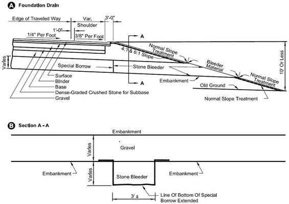
Notes:
- Bleeders are to be placed at 200-foot intervals, at low points, and at approximately 50 feet before and after each low point, and/or as directed by the engineer.
- See special provisions for bleeders, special borrow.
- Bleeders are not placed on 2:1 fill slopes. Special borrow is extended to slope.
Source: MassDOT
Figure 8-9 shows the horizontal placement of stone bleeders along a roadway. The bleeders should be angled approximately 60° from the roadway, pointing towards the direction of flow.
Figure 8-9: Location of Foundation Drains
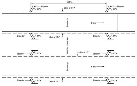
Notes:
- Bleeders are to be placed at 200-foot intervals, at low points, and at approximately 50 feet before and after each low point, and/or as directed by the engineer.
*End of special borrow.
Source: MassDOT
Figure 8-10 shows the location of a subdrain in a roadway cut section with the subdrain placed below and at the outside edge of the special borrow, allowing groundwater to flow through the special borrow and away from the subbase through the subdrain.
Figure 8-10: Subdrains in Earth Cuts
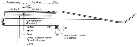
Notes:
- See special provisions for special borrow specification.
- See construction standard 102.1.0 for treatment in rock cut, except that the subdrain should be placed in a “sump” as shown above.
Source: MassDOT
Figure 8-11 shows three illustrations of subdrain locations with different median types. The first shows a raised median with the subdrain located below the special borrow at the center of the section. The second shows a 28-foot to 44-foot median with the subdrain located below the special borrow at the center of the section. The third shows a 44-foot to 88-foot median with subdrains located below and at the end of the special borrow, which ends after the pavement structural section on either side of the median.
Figure 8-11: Subdrains in Medians
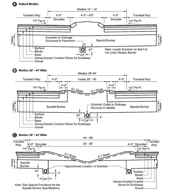
Source: MassDOT
Stormwater Control Measures
Stormwater control measures are often designed as part of the stormwater management system to improve water quality, increase groundwater recharge, and detain flows. Please refer to the MassDOT Stormwater Design Guide for detailed information on the use, planning, retrofit, and design of stormwater control measures.
Special Designs
On occasion, it may be necessary to use special hydraulic designs that may include:
- Siphons
- Bradley head inlets
- Flood control gates
- Debris control structures
- Detention basin outlet structures
- Sediment chambers
The designer should review any available technical publications which discuss these designs. The use of siphons to convey streams in cross-culverts is discouraged.
8.5 Erosion Control During Construction
During a highway construction project, soil erosion can be a major contributing factor to environmental pollution. To minimize the effect of sedimentation, scour, turbulence, washouts, etc. during construction operations, temporary measures and sometimes permanent controls must be provided.
Depending on the proximity of existing wetland resource areas, the project may be subject to the Wetlands Protection Act under MGL Chapter 131, Section 40. If that is the case, then the design of erosion and sedimentation controls will need to be reviewed and approved by the local Conservation Commission.
In 1999, the EPA extended coverage of the NPDES stormwater program to small MS4s through the Phase II rule. The NPDES program includes a Construction General Permit to address discharges from construction activities that involve land disturbance of 1 acre or more. Coverage under this permit requires filing of an NOI with the EPA Region 1 office and preparation of a site-specific SWPPP including proposed erosion and sediment controls and their locations.
In addition to affecting MassDOT construction activities, the NPDES Phase II rule applies to MassDOT as an “operator of MS4s.” Phase II requires implementation of six minimum control measures (MCMs) including the following elements: 1) public education and outreach, 2) public participation/involvement, 3) illicit discharge detection and elimination, 4) construction site runoff control, 5) post-construction runoff control, and 6) pollution prevention/good housekeeping. This section addresses the requirements of MCM 4 on construction site runoff control.
The type and design of the controls will vary depending on the environment that is to be protected and the specific cause of the potential environmental degradation. The protective measures may consist of, but not be limited to:
- Sedimentation basins for the protection of downstream rivers, lakes, streams, and ponds
- Temporary earth berms and slope drains to control heavy runoff, thus preventing washouts
- Ditches at the bottom of slopes
- Temporary check dams at waterway crossings
- Filters at drain inlets
- Energy dissipators at culvert outlets (e.g., splash pads, bulk stone deposits, etc.)
- Silt fences
- Compost filter tubes or straw bales
The first priority in controlling erosion is to prevent displacement of the soil. When this is impractical, control measures should be designed to collect the displaced soil in a sediment control system. The most susceptible areas include cut-to-fill transitions, open channels, culvert inlets and outlets, steep slopes, borrow pits, and haul roads. Sandy and silty soils are the most susceptible to erosion; clay and gravel are the least susceptible. The designer should review the Soils Report to identify the type of soils likely to be exposed.
The construction plans and specifications may include various measures to prevent or minimize erosion and sedimentation:
- Sequencing the work to minimize the extent of land disturbance at one time
- Constructing permanent drainage features (channel linings, seeding, sodding, mulching, energy dissipators, etc.) as soon as possible
- Designing protection to closely follow the grading operation, for example, mulching and seeding deep cuts and high fills as the work progresses
- Minimizing the area and duration of exposed soil
- Reducing the velocity and volumes of runoff on bare soil with temporary check dams and diversions
- Trapping or filtering out sediment before it leaves the construction area
Many types of protective designs can be adapted to meet a particular condition. The temporary control measures generally include vegetation, water runoff diversion, sedimentation checks, and sedimentation basins. In some cases, the designer may have to develop innovative measures to control erosion and sedimentation.
Generally, the various schemes detailed in Chapter 20 of the AASHTO Drainage Manual and Chapter 3: Erosion and Sediment Control in Highway Construction in AASHTO Highway Drainage Guidelines, 4th Edition (2007) can be applied. Guidance on sedimentation basins can be found in NCHRP Synthesis 70, Design of Sedimentation Basins, Transportation Research Board, June 1980.
The designer should also refer to the Massachusetts Erosion and Sediment Control Guidelines for Urban and Suburban Areas, Prepared by Franklin, Hampden, Hampshire Conservation Districts, for the MassDEP, 1997 (revised 2003).
Vegetation
Vegetation applied soon after the grading operation is highly effective in erosion control. The vegetation can be temporary or (preferably) permanent. Temporary vegetation is practical when the final grading operation cannot be immediately completed, and the area will be exposed for a considerable length of time (i.e., more than one month).
Both permanent and temporary vegetation will require these considerations:
- Fertilization (temporary seeding requires about 400-700 lbs/acre)
- Mulch or binder (including straw, bituminous, and/or jute mesh)
- Topsoil, loam or plantable soil (4-in minimum thickness)
- Sod at critical locations (embankment grade breaks, ditch bottoms, and other susceptible areas)
- Other special vegetative applications (see Chapter 13 for details)
Flow Diversion
Diversion Channel
These are temporary channels to divert water around an ongoing construction site for a permanent drainage structure. These keep the worksite dry and therefore minimize the chance for erosion. Diversion channels are normally used where structures larger than a 36-inch pipe are being installed in a natural stream. The construction sequence should be:
- Excavate and shape the diversion channel, leaving plugs or berms at both ends.
- Install channel linings as required.
- Remove plug from diversion channel (downstream first) and plug permanent channel location.
- Construct the permanent drainage structure.
- Remove plugs (downstream first) and divert flow to the new channel.
- Divert the flow through permanent structure.
- Salvage material and obliterate diversion channel.
The size of the diversion channel will depend on the discharge and channel shape, slope, and roughness. The procedures in Chapter 6 in HEC #22 on Roadside and Median Channels can be used to design the temporary ditch. A 2-year or 5-year runoff frequency should be used. Figures 8-12 through 8-14 illustrate the typical design of a diversion channel.
Figure 8-12 shows a diversion channel placed above a cut slope, beyond the limits of excavation. The ditch should be seeded and protected with temporary lining, and a seed and mulch berm should be located on the downslope edge of the ditch.
Figure 8‑12: Temporary Diversion Channel and Berm (Cross Section)
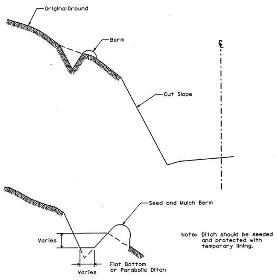
Note: A temporary diversion channel can also be used beyond the bottom of a fill slope
Source: Best Management Practices for Erosion and Sediment Control, FHWA, Figure 5.3
Figure 8-13 shows a diversion channel located downslope from a fill slope. The ditch should be located approximately 6.5 to 10 feet from the toe of the fill slope, and a seed and mulch berm should be placed along the downslope edge of the ditch. The ditch should be seeded and protected with temporary lining.
Figure 8-13: Temporary Diversion Channel and Berm (Cross Section)
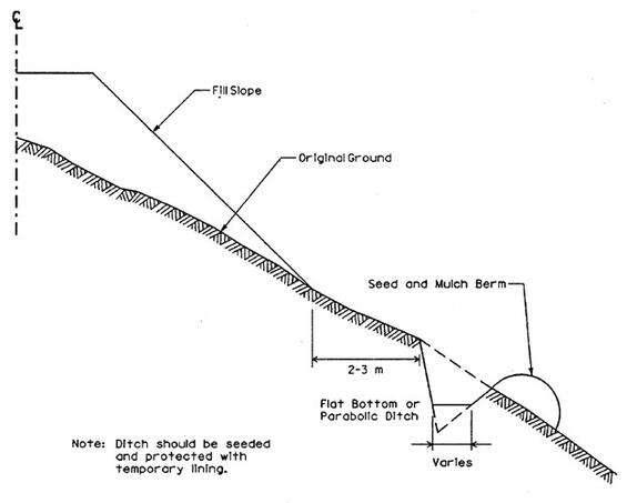
Source: Best Management Practices for Erosion and Sediment Control, FHWA, Figure 5.4
Figure 8-14 shows a diversion channel that redirects flow around a proposed culvert. If a temporary culvert is not used, a silt fence is required along the entire length of the channel. If a temporary culvert is used, a silt fence is required around the around the outlet.
Figure 8-14: Temporary Diversion Channel for Culvert Installation
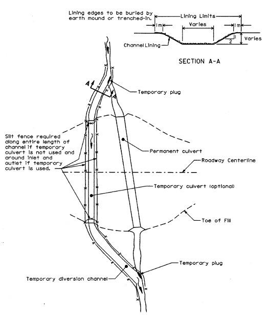
Source: Best Management Practices for Erosion and Sediment Control, FHWA, Figure 5.5
Temporary Slope Drain
These systems carry water from the work area to a lower elevation, typically down an embankment. They help prevent erosion of the slope until permanent protection is established. Slope drains may be metal pipes, half-round pipes, or paved ditches. They should be placed:
- Every 500 feet on a 2% grade
- Every 200 feet on a 4% grade
- According to field conditions on 5% or steeper grades
- At all low points
Minimum pipe sizes are 12 inches for metal pipes, and 18 inches for half-round corrugated metal pipes.
A protective treatment (stone revetment) should be provided at the outlet of a temporary slope drain. The inlet of a metal pipe should have a prefabricated metal inlet structure. Figure 8-15 illustrates a typical site and design for a temporary slope drain for conveying flow from the area of fill to the toe of the slope. The slope drain should include a temporary berm and metal end section at the top of the fill section, and loose rip rap at the outlet of the pipe. The drain should be extended vertically as required to coincide with the height of the embankment.
Figure 8-15: Temporary Slope Drain (Elevation View)
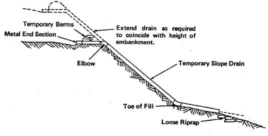
Source: Best Management Practices for Erosion and Sediment Control, FHWA, Figure 5.6
Sedimentation Checks
Several types of sedimentation checks are available for use during construction, as described in the following sections.
Silt Fences
These are fences made with a geotextile filter fabric that trap sediment before it leaves the construction area. Silt fences can be prefabricated with geotextile filter fabric material which allows for easy installation. The fence is a minimum of 36-inch high and has wood stakes at 6-10 foot spacing. Commercial filter fabrics should be used with the approximate permeability of a #50 sieve. See MassDOT Construction Standards for construction details. Figures 8-16 and 8-17 illustrate typical installations where silt fences are applicable. As shown in Figure 8-16, when a silt fence is used as perimeter control along a roadway fill section, the silt fence should be located approximately 3 to 6.5 feet downslope of the toe of the fill.
Figure 8-16: Silt Fence as a Perimeter Control
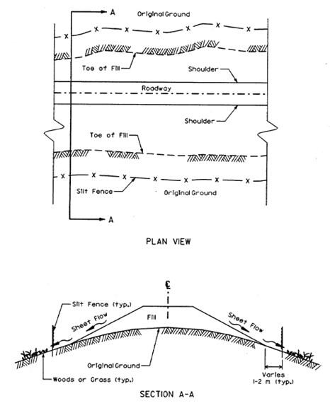
Source: Best Management Practices for Erosion and Sediment Control, FHWA, Figure 5.11
As shown in Figure 8-17, when a silt fence is used to protect a waterway, it should be placed approximately 3 to 6.5 feet downslope from the fill section and before the top of bank of the stream. The silt fence on the slope side should be placed perpendicular to the fill at the end of the fill section and downstream of the direction of flow.
Figure 8-17: Silt Fence Protecting Waterway
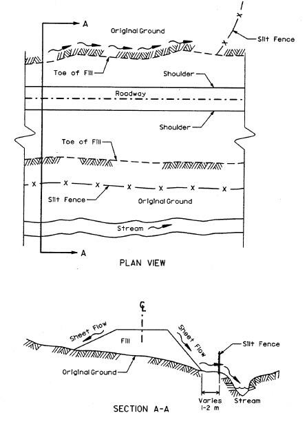
Source: Best Management Practices for Erosion and Sediment Control, FHWA, Figure 5.12
Compost Filter Tubes or Straw
These are used to reduce flow velocity and intercept the sediment before it leaves the construction area. Typical applications include:
- Bottom of embankment
- Temporary slope drain outlet
- Filter cores for temporary check dams
- Around storm drain inlets
- Behind silt fences
Straw bales should be tied with biodegradable twine. They should be anchored with 2” by 2” by 4’ wood stakes (two per bale). Compost filter tubes should be composed of biodegradable fabric and should be staked as necessary. They should have firm contact with the ground to prevent flow underneath the tubes.
Both straw bales and compost filter tubes should last three to six months and must be replaced when clogged with sediment or deteriorated. See MassDOT Construction Standards for construction details.
Temporary Check Dams
These are barriers made of filter cloth and straw bales which reduce flow velocity and trap the sediment. They are normally used below small drainage structures (less than 38-inch diameter pipe). Temporary check dams may also be used below larger structures if a diversion channel is impractical. Riprap may be necessary on the downstream side of the dam to protect the stream bed from scour.
Sediment Basins
Sediment basins are detention areas used to intercept runoff and allow sediments to settle out during construction activities. They are installed to protect downstream streams, rivers, ponds and lakes from the excess sediment produced during construction. The basin can be produced by excavation, in a natural depression, or with an impoundment berm of some type. Typical locations in natural drainage- ways include the bottom of embankments, the lower end of waste or borrow areas, or at the downgrade area of a cut section. Sediment basins typically consist of an impoundment or embankment, a pipe outlet, and an emergency spillway.
Types of Sediment Basins
Temporary Sediment Traps
These are small basins intended for short-term use (overnight to a few weeks). Typical dimensions might be 5 feet by 10 feet and 3 to 5 feet in height. Many temporary sediment traps might be used at a construction site. They can remain in place until they obstruct construction operations or fill up with sediment deposits, when they can be either cleaned out or replaced with more traps.
Temporary Sedimentation Basins
These are intended to remain operational during the entire construction period. Therefore, their locations must not interfere with construction operations. During its life, it may be cleaned out periodically.
Permanent Sedimentation Basins
These are designed for use during construction, but they are intended to remain as permanent facilities. A permanent basin may be used to detain stormwater once it is cleaned out after construction; however, they are typically not used as infiltration basins to treat and recharge stormwater into the ground due to siltation of the underlying soils that occurs during construction.
Sedimentation Basin Design Criteria
The following criteria apply to the design of sedimentation basins:
- Sedimentation basins should be constructed before any grading operations begin and should not interfere with construction activities.
- The basin should be accessible for easy cleanout.
- The basin should not be constructed on any watercourse.
- In general, several small sediment traps typically work better than a larger sedimentation basin.
- The size of a temporary sedimentation trap should be determined on a case-by-case assessment of the drainage area size and duration of use.
The size of a sedimentation basin should be determined by:
V = 1815*A
Where: V = volume of basin, cubic ft
A = drainage area, acres
1815 = volume (in cubic ft) of 0.5 inch runoff per acre drained
- For projects under the jurisdiction of the Construction General Permit and require a SWPPP, sedimentation basins must be designed to provide storage for either the calculated volume of runoff from a 2-year, 24-hour storm or 3,600 cubic ft per acre drained.
If the basin will eventually discharge into a reservoir used for drinking water, the storage capacity of the basin should be increased and determined on a case-by-case basis. The water level in the basin, based on the calculation, should be no less than 1 foot to the elevation of the overflow spillway and preferably no less than 2 feet. If practical, the length of the basin should be at least twice its width.
The earth berm surrounding the basin should meet the following criteria:
- Berm height should be minimized. When possible, construct basins entirely in cut to eliminate the need for berm.
- The height of the berm should not exceed 10 feet.
- The minimum top width is 8 feet for a 10-foot height.
- The recommended slope is 2:1 or flatter on each side.
- The composition of the earth berm should be based on recommendations from the MassDOT Geotechnical Section.
- A grate or cage should be placed on top of the riser pipe for safety.
Additional information on the design of small earth dams can be obtained from Technical Release 210-60 Earth Dams and Reservoirs prepared by the U. S. Department of Agriculture, Natural Resources Conservation Service, Conservation Engineering Division, March 2019.
8.6 References
- Applications for Department of the Army Permits for Activities in Waterways, EP1145-2-1, U.S. Army Corps of Engineers, October 1974 (resource currently unavailable on website)
- Procedures for Coordinating Highway Encroachments on Floodplains With FEMA, FHWA, June 7, 1982.
- National Flood Insurance Program, Flood Insurance Manual, FEMA, April 2024.
- National Flood Insurance Program Community Rating System, Coordinator’s Manual, FEMA. (resource currently unavailable on FEMA website)
- National Flood Insurance Program Community Rating System, Addendum to the 2017 Coordinator’s Manual, FEMA.
- Magnitude of Flood Flows at Selected Annual Exceedance Probabilities for Streams in Massachusetts, SIR 2016-5156, U.S. Geological Survey.
- StreamStats, U.S. Geological Survey.
- NOAA Atlas 14 Point Precipitation Frequency Estimates: MA, U.S. National Oceanic and Atmospheric Administration.
- Part 630 Hydrology National Engineering Handbook, U.S. Natural Resources Conservation Service.
- Technical Release No. 55, Urban Hydrology for Small Watersheds, U.S. Natural Resources Conservation Service.
- Technical Release No. 20 Computer Program for Project Formulation – Hydrology, U.S. Natural Resources Conservation Service.
- Introduction to Highway Hydraulics, Hydraulic Design Series No. 4 (HDS #4), Federal Highway Administration.
- Hydraulic Design of Highway Culverts, Hydraulic Design Series No. 5 (HDS #5), Federal Highway Administration.
- Hydraulic Design of Safe Bridges, Hydraulic Design Series No. 7 (HDS #7), Federal Highway Administration.
- Design of Roadside Channels with Flexible Linings, Hydraulic Engineering Circular No. 15 (HEC #15), Federal Highway Administration.
- HY-8 Culvert Hydraulic Analysis Program, Federal Highway Administration.
- Hydraulic Design of Energy Dissipators for Culverts and Channels, Hydraulic Engineering Circular No. 14 (HEC #14), Federal Highway Administration.
- WPCF Manual of Practice No. 9, Design and Construction of Sanitary and Storm Sewers, Water Pollution Control Federation and the American Society of Civil Engineers, 1969.
- FHWA-TS-80-224, Highway Subdrainage Design, Federal Highway Administration.
- FHWA NHI-05-037, Geotechnical Aspects of Pavements, FHWA.
- Best Management Practices for Erosion and Sediment Control, Federal Highway Administration, 1995.
- NCHRP Synthesis 70, Design of Sedimentation Basins, Transportation Research Board, June 1980.
- Highway Drainage Guidelines, AASHTO.
- Drainage Manual, AASHTO.
- Stream Stability at Highway Structures, Hydraulic Engineering Circular No. 20 (HEC #20), Federal Highway Administration.
- Urban Drainage Design Manual, Hydraulic Engineering Circular No. 22 (HEC #22), Federal Highway Administration.
- Culvert Design for Aquatic Organism Passage, Hydraulic Engineering Circular No. 26 (HEC #26), Federal Highway Administration.
- Massachusetts Stormwater Handbook Volumes 1, 2, and 3, MA Department of Environmental Protection.
- MassDOT Stormwater Design Guide, MassDOT.
- MassDOT Construction Standards, MassDOT.
- Massachusetts Erosion and Sediment Control Guidelines for Urban and Suburban Areas, Prepared by Franklin, Hampden, Hampshire Conservation Districts, for the MA Department of Environmental Protection.
- Technical Release No. 210-60 Earth Dams and Reservoirs, U.S. Natural Resources Conservation Service.
- Hydrology Handbook for Conservation Commissioners, MA Department of Environmental Protection.
- Bridge Manual, MassDOT Highway Division.
- Hydraulics Design Manual, Oregon Department of Transportation.
8.7 Additional Resources
This section provides the following nomographs in a separate PDF that can be used by designers for preliminary sizing of stormwater conveyances:
- Design nomograph for calculating headwater depth for box culverts under inlet control conditions (Source: FHWA HDS-5, Chart 8B)
- Design nomograph for calculating headwater depth of a concrete box culvert flow full with a Manning’s roughness coefficient of 0.012 (Source: FHWA HDS-5, Chart 15B)
- Design nomograph for calculating the headwater depth for concrete pipe culverts under inlet control conditions (Source: FHWA HDS-5, Chart 1B)
- Design nomograph for calculating the headwater depth for concrete pipe culverts flowing full with a Manning’s roughness coefficient of 0.012 (Source: FHWA HDS-5, Chart 5B)
- Design nomograph for calculating flow capacity, pipe diameter, slope, and velocity of a pipe flowing full given two known values and assuming a Manning’s roughness coefficient of 0.013 (Source: Oregon DOT Hydraulics Manual, Figure 8-19)
- Design nomograph for calculating the capacity of a circular corrugated pipe flowing full given the diameter and slope of the pipe (Source: Oregon DOT Hydraulics Manual, Figure 8-20)
- Design nomograph for calculating discharge for gutter with near vertical curb and single cross slope (Source: Oregon DOT Hydraulics Manual, Figure 8-14)
- Design nomograph for calculating discharge for gutter with two cross slopes (Source: Oregon DOT Hydraulics Manual, Figure 8-16)
- Design nomograph for calculating discharge for gutter with near vertical curb and two cross slopes (Source: Oregon DOT Hydraulics Manual, Figure 8-17)